Project update 6 of 23
Manufacturing Progress, Enclosure Pics, Software Development, and Some Testing
by KrakenRF IncManufacturing Updates
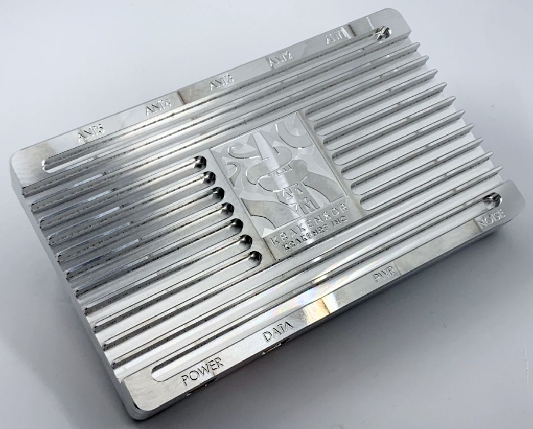
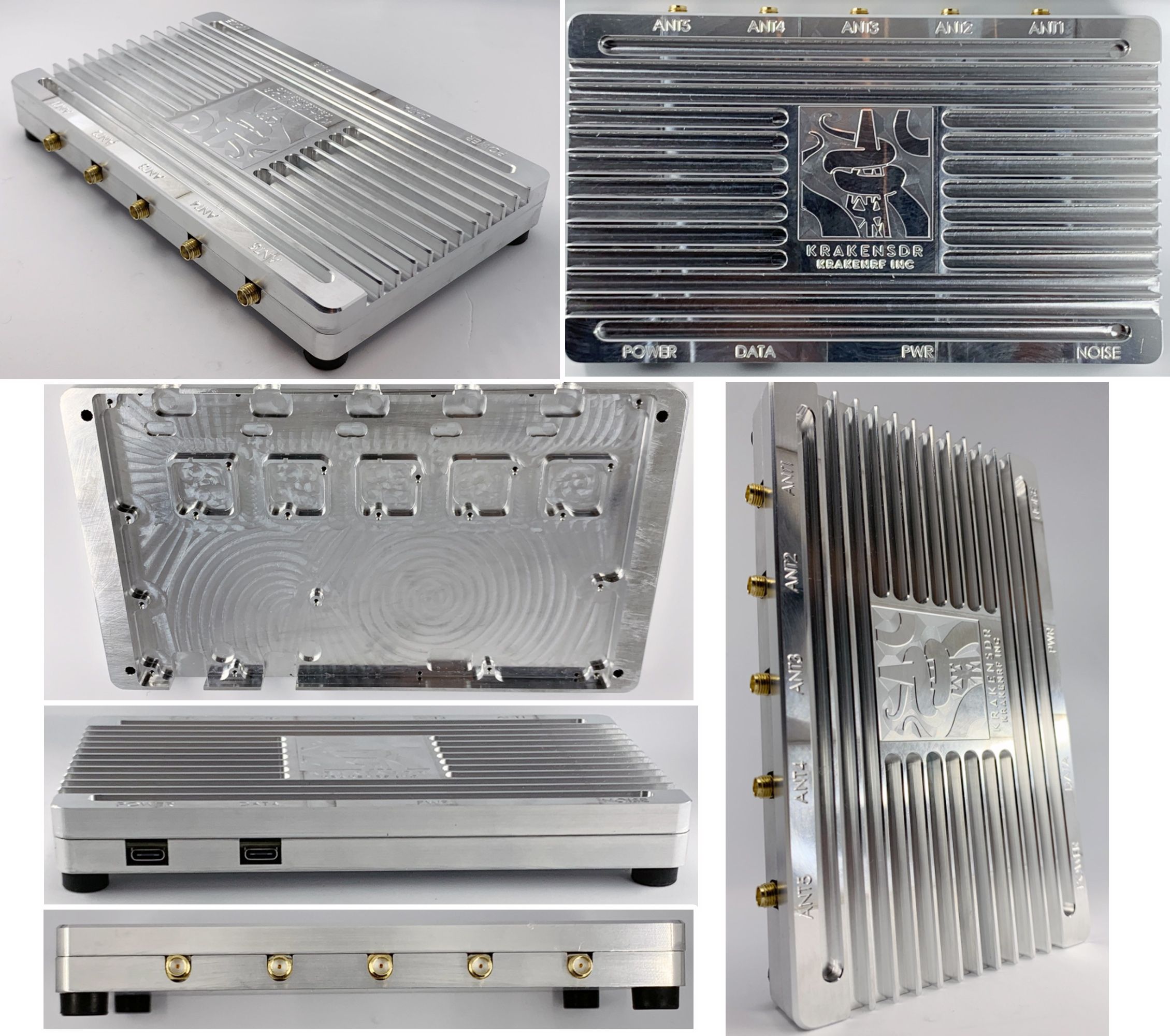
We have received prototypes of the latest metal enclosure and they are looking great! This CNC’d aluminum enclosure, which is critical to the proper functioning of KrakenSDR, acts as:
- Thermal mass to dampen phase changes from rapid temperature changes
- A heat sink to keep overall PCB temperatures down
- An RF shield to prevent RF leakage from reaching the PCB
Below are some photos of the latest enclosure cut. This is fairly representative of what the final product will look like, although these prototypes are raw aluminum. In the final production model, the aluminum surface will have a nicer finish.
Software Updates
Updates to the software continue, and we have recently completed changes that allow us to decimate down to very small bandwidths, enabling better support for narrowband CW signals. We are also working on optimizing the web GUI update rate.
Work on the core features of the DFing code is almost complete, so we expect to be releasing that code from the development branches within the next few weeks. We will also provide an SD Card image for KerberosSDR owners so that they can begin testing early.
Notes on External Component Phase Distortion Info
We have received some questions asking how external components such as amplifiers and filters can distort phase, and hence if they can be used.
While the KrakenSDR combined hardware and software system can compensate for sample and phase differences within it’s own circuitry, it cannot compensate for differences that occur in external components, such as antennas, cables, LNAs and filters. For this reason it is important that all external components are identical on all five ports. This also means that antenna coax cables must be cut to identical lengths.
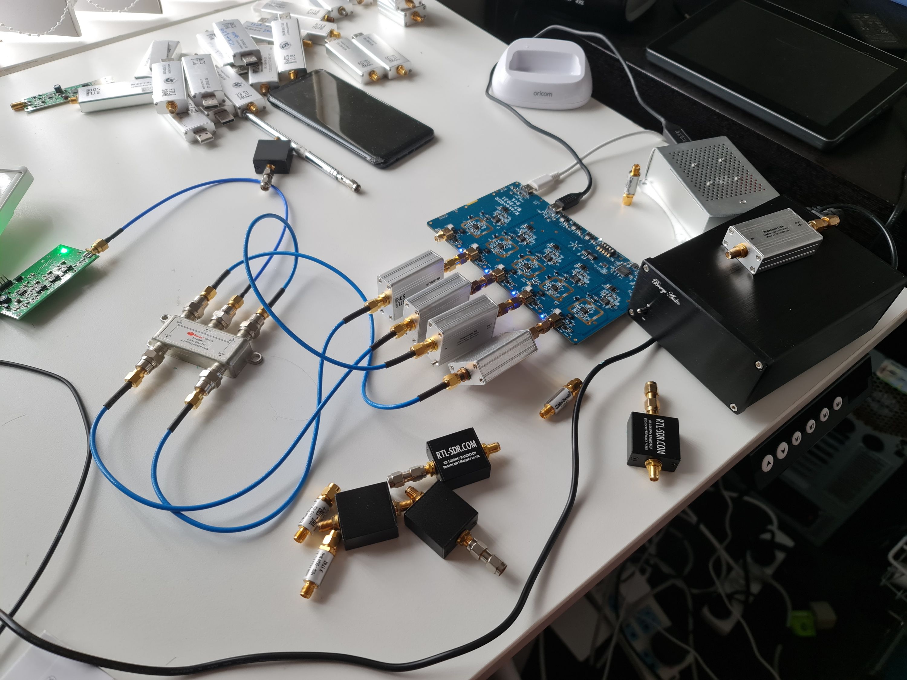
To confirm that the difference in phase delays between identical components is mostly negligible, we set up an experiment. The KrakenSDR is fed an external noise signal, distributed into four inputs, via a four-way splitter. When we calibrate using the noise source, the bearing should point to zero degrees, and it does. Adding four external components such as LNAs introduces some minor phase delay variances, which we can then measure in software.
Test 1: Changing Coax-Lengths
The first test involves extending the coax length on the channel-four input by three centimeters via the use of an adapter.
- At 100 MHz the 3 cm addition shifts channel four's phase by 6 degrees. The resulting distortion in the compass bearing is about 0.8 degrees.
- At 400 MHz the 3 cm addition shifts channel four's phase by about 15 degrees. The resulting distortion in the compass bearing is about 1.5 degrees.
- At 800 MHz the 3 cm addition shifts channel four's phase by about 40 degrees. The resulting distortion in the compass bearing is about 3.8 degrees.
- At 1600 MHz the 3 cm addition shifts channel four's phase by about 75 degrees. The resulting distortion in the compass bearing is about 8 degrees.
This test shows how important it is that coax cable lengths be as identical as possible. A few centimeters of difference can result in several degrees of distortion. Secondly, we can see that, as the frequency of interest increases, the compass bearing is shifted more. This means that precision requirements of the cable lengths become even more strict at higher frequencies. In the VHF band, you can get away with a few centimeters of tolerance, but in the upper UHF band and beyond, you’ll want millimeter tolerances.
Test 2: External LNAs & Filters
In real world testing, no noticeable changes to the RDF compass bearing output were noticed when external components like filters and LNAs were added, but we wanted to quantify this a bit better. In this test we added four identical external components to the input and measured the distortion to the output.
The first test was with four broadcast FM band-stop filters.
- At 100 MHz the channel phase shifts were at most 3 degrees out. This resulted in a 0.2 degree distortion to the compass bearing.
- At 800 MHz the channel phase shifts were at most 6 degrees out. This resulted in a 0.3 degree distortion to the compass bearing.
The second test was with four wideband LNAs powered via the on board bias tees.
- At 100 MHz the channel phase shifts were at most 4 degrees out. This resulted in a 0.5 degree distortion to the compass bearing.
- At 800 MHz the channel phase shifts were at most 8 degrees out. This resulted in a 0.3 degree distortion to the compass bearing.
Our conclusion is that, as long as the components are identical, there is negligible distortion caused by minute manufacturing differences. Of course it’s possible that some RF components, such as hand-made filters or filters that require hand tuning, could have larger differences that could affect the phase much more.
FAQ Updates
Our FAQ has also been updated with this weeks questions.
If you’ve emailed a question and we haven’t replied yet, we will get back to you within a few days time.


