Project update 7 of 23
EU Orders, Software Updates, and Antenna-Array Spacing Information
by KrakenRF IncCE EU Ordering Updates
If you had trouble placing an order from the EU and received errors about a missing CE certification, please give it another try. There appears to have been a misconfiguration in Crowd Supply’s ordering system that incorrectly excluded EU backers for approximately five days. That misconfiguration has since been fixed.
For clarification, KrakenSDR will have CE certification, making it legal to sell and use within the EU.
Software Updates
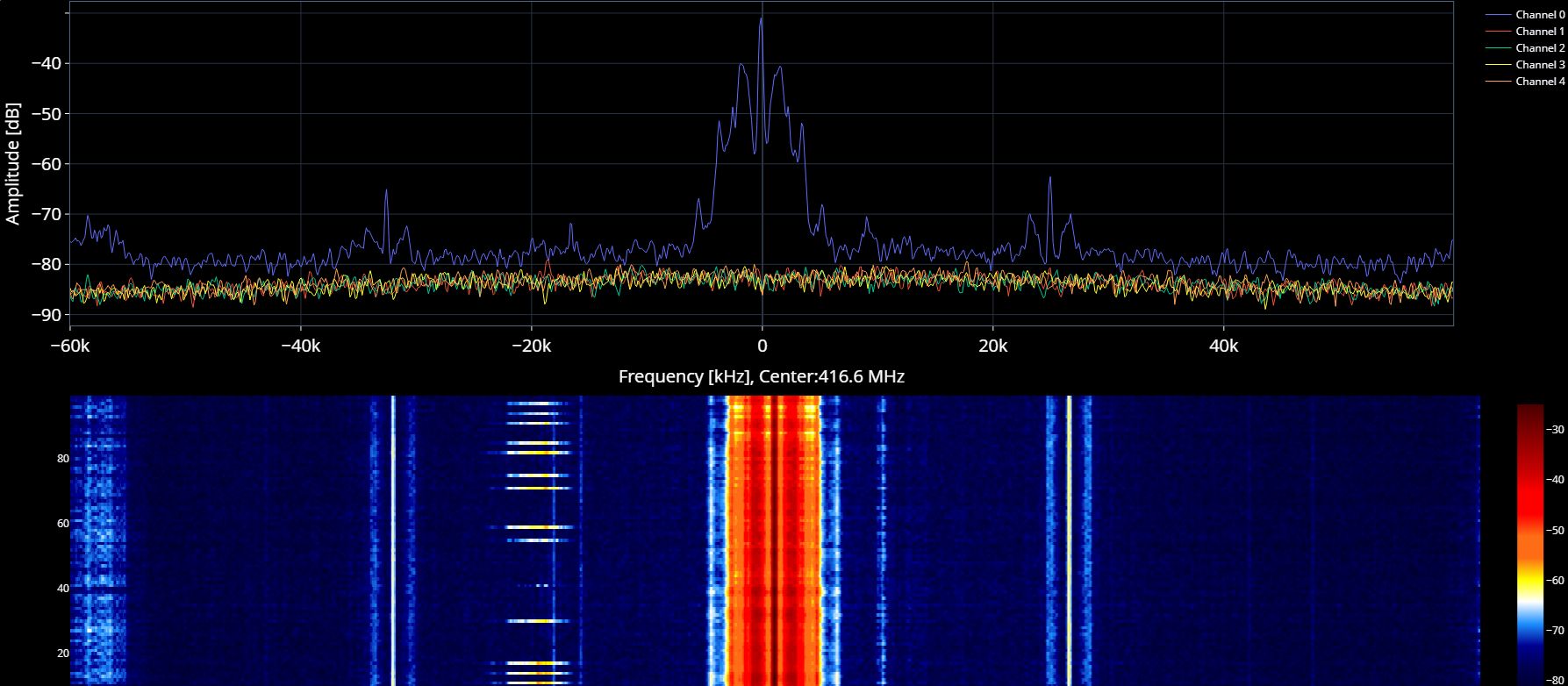
We have recently been testing the software on a Raspberry Pi 4 with the new 64-bit Raspbian Bullseye OS. Results so far have been great with the 64-bit OS and the extra 300 MHz that the new OS unlocks giving a decent boost to calculation speed. We have also been working on updating the software to produce faster plots, and to add a waterfall display to the spectrum display.
The direction finding software stack is close to being feature complete and tested for direction finding a single frequency at a time. Future work aims to unlock the capability to direction find multiple signals within a the maximum 2.56 MHz bandwidth, and possibly even cycling between multiple frequencies in a larger bandwidth.
Work on a multiplatform networking capable mapping program has also now begun. This will allow for multiple fixed and mobile KrakenSDR units to upload bearing data onto a server.
Antenna-Array Spacing Information
There has been some interest in understanding what sort of antenna spacing is required for radio direction finding. There are currently two supported ways to arrange antennas, the Uniform Linear Array (ULA) and the Uniform Circular Array (UCA).
With an ULA array, the antennas are simply spaced out in a straight line. The interelement-spacing should be at most 0.5 * lambda, where lambda is the wavelength of the frequency of interest. Any larger and you will be getting ambiguous results. In practice, generally a multiplier between 0.2 and 0.5 will work, with values closer to 0.5 giving more accurate results in the presence of multipath. So generally when you have an array spaced for a certain frequency, you can RDF on lower frequencies but not higher.
The major disadvantage of a linear array is that you cannot tell if the signal source is coming from in front, or behind the array.
With an UCA array, the antennas are instead arranged in a circle, and it’s possible to determine the bearing from 360 degrees around the array. The radius of the circle again depends on the frequency wavelength and the spacing multiplier, and the number of elements in the array. The formula for the array radius is…
radius = (lambda * spacing multiplier) / sqrt((2 * (1-cos(360/N)))
…where N is the number of elements in the antenna array.
Again the spacing multiplier needs to be less than 0.5 to avoid ambiguous bearing results. A spacing multiplier of about 0.3 is a reasonable choice to go with. With that choice made, the radius required for various frequencies is shown in the table below:
| Frequency | Radius |
|---|---|
| 25 MHz | 306 cm |
| 50 MHz | 153 cm |
| 144 MHz | 53 cm |
| 160 MHz | 48 cm |
| 433 MHz | 18 cm |
| 600 MHz | 13 cm |
| 900 MHz | 8.5 cm |
| 1100 MHz | 7 cm |
| 1700 MHz | 4.25 cm |
As you can see for the lower frequencies array sizing becomes rather unreasonable, unless you have lots of free space. When working at those low frequencies and in the HF bands other direction finding techniques like distributed TDoA (like what the KiwiSDR project uses) become much more feasible.
We have created an excel sheet that you can use to calculate the radius and array element coordinates for a 5-element array, and it can be downloaded from here. Simply enter the frequency that you are interested in in the yellow box, and then based on your choice of the spacing factor, enter the calculated radius in the yellow box on the right to calculate coordinates for an antenna array.

