For better or worse, it’s good to reach the end…
What Does It All Mean?
For you, dear reader / potential backer, it actually doesn’t make that big of a difference whether you order your Jumperless V5 before or after crowdfunding ends. One of the many awesome things about doing this with Crowd Supply is that they order a bunch of units to keep in stock. The price will be going up, though, when the campaign ends later on today. Jumperless V5 will still be available on Crowd Supply, but it’ll cost a bit more, and you’ll have to pay for shipping yourself.
For me, the end of the campaign means I get to start ramping up for full-scale production pretty soon. The goal is to get first batch (which should be enough to cover all the campaign backers’ orders) assembled and shipped to me before Chinese New Year. That’s not some arbitrary goal post, CNY / Spring Festival is a (well-earned) holiday that starts on January 29th next year and effectively means nothing is happening in China for the entire month of February.
It’s a fairly tight timeline for the number of different manufacturers involved, so to give me some wiggle room to have a last round of final-production prototypes made, I went to Elecrow and said "here is all the money I have until the campaign ends, is this enough to source the parts before I send you finalized design?" and they were like (I’m paraphrasing here, in AI Jeff Geerling’s voice) "naw dawg, but it’s cool homie, we gotchu fam." Elecrow’s been an amazing CM for both versions of Jumperless, and it’s really nice to know they have my back doing whatever it takes to get them made to my absurdly picky standards and shipping on time.
Move Fast & Fix Things
Thus far I’ve kind of avoided talking too much about things I haven’t fully implemented yet. But this is the last update before the campaign ends so I should probably talk about some of the features that will be finished by the time you get your Jumperless V5, and a few that are planned to come out in a future firmware update. These are listed roughly in the order they’ll be worked on, but all but the last one should be ready by the time you get yours.
La Résistance
Analog crossbar switches have some resistance, roughly totaling to 85Ω after the two hops though a crossbar needed to make a connection. And if all the direct paths are taken, it’ll need 4 hops to go through an intermediate chip, so 170Ω.
For signals, this has a negligible effect (if no current is flowing, the voltage drop is zero), but for connections used to power anything that draws a good deal of current, this sucks, and I wish it were 0Ω.
I had just kinda accepted this as a limitation of physics / economics / not making this thing take up an entire desk. Like, if I wanted to use relays or some other discrete part, I would need (12 x 128 =) 1,536 individual switches.
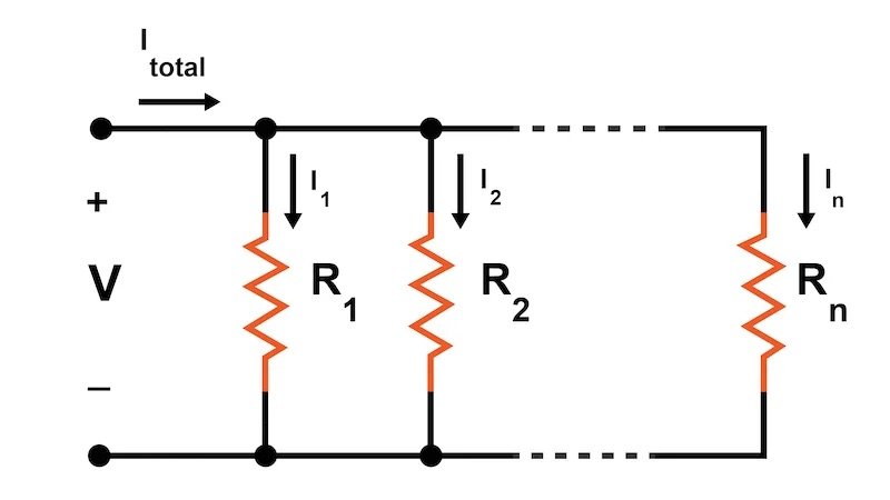
But wait, unless you’re trying to connect every breadboard row to every other, most of the available connections are unused, just chillin’. And adding resistors in parallel decreases the total resistance by
So once the Jumperless finds a path for all the connections it was asked to make, we can have it go through again and fill up all the unused paths with redundant parallel connections to bring the resistance way down. You’ll be able to set a higher priority for connections that need to carry more current, probably with a long press on the probe button, but in general it’ll just do this without you having to think about it.
Aha! Using physics to beat physics!
Some firmware ideas demand to be written immediately after thinking of them, this one came up on the 4 hour drive home from Supercon, so I turned off the Philip K. Dick audiobook I was listening to and started working out how I was going to pull this off in my head. As soon as I finish writing this campaign update, I’m starting this firmware update.
A Menu Option We Can Blame on Benjamin Franklin
So far, the INA219 current sensors haven’t really gotten the love they deserve, but that’s going to change soon. I have been using them to detect the switch position on the probe by determining which of the two power sources are drawing the current needed to drive the LEDs (it swaps power sources when you switch from Select to Measure to save pins to get it down to four connections in a TRRS cable, it’s a whole thing), but there’s a lot more they can do.
You know those little "ants" they put on wires in simulations to show the flow of current?
This is a transistor-level simulation of a CMOS analog switch if you’re curious about what’s going on inside a Jumperless
Now you can have those on your breadboard too! There’s just one routable as a current sensor (the other is for measuring resistance / current draw from the DACs), so you’ll be able to poke around with the probe and it’ll show you the current between any 2 places.
Another funny thing is that means I should put a menu option for which current flow convention to use. When Benjamin Franklin theorized that electric charge was the presence or absence of something he knew there wasn’t really a way to tell whether the rabbit fur or the glass rod was the one gaining the something, so he just picked one. To the joy of future textbook publishers everywhere, he guessed wrong.
So there will be a setting that does something like this:
Probe Fu
Watching people use Jumperless V5 at Supercon gave me some new ideas for cool things you can do with the probe. Having the tip be arbitrarily routable to anything means it can really do anything we can come up with.
Here’s a couple that I think will be super useful and likely added before they ship:
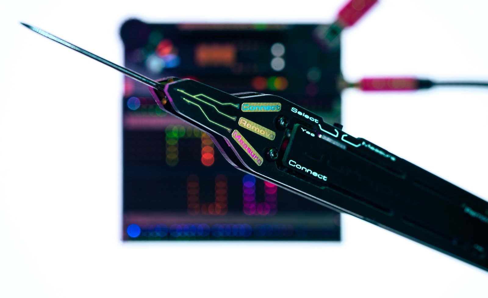
Using it as a logic probe. It already has 3 LEDs, so it can use them to show Floating, Low, or High. The colors I happened to pick are perfect, white in the middle for floating, pink at the top for high, and cyan at the bottom for low.
A nicer interface for toggling any of GPIO pins, just tap any net that has a GPIO connected, and the Connect (front) button will drive it low, and Remove will drive it high (I’m imagining the probe pointed downwards at the board so top is high and bottom is low.)
I’ll definitely think of more, but if you have a good idea, come drop it in the Jumperless Discord.
Unleashing Your Inner User Manual
I’m one of those weirdos that usually at least takes a quick look at the user manuals that come with things, but I don’t like when they’re necessary to use it at all. Jumperless will come with some printed "Getting Started" guide to get you up to speed on using the probe, getting into menus, setting up the app, etc. But for things beyond the basics, development on the Jumperless firmware moves fast, I need docs that are as software-configurable and "liquid" as the Jumperless itself. The lazy way is just to be like a restaurant and rely on a QR code that takes you to the online docs. That will definitely be a thing, but I also want something that feels more natural.
So there will be step-by-step guides that will display on the breadboard LEDs to walk you through how to do things. As well as help pages for each option over the serial terminal. What’s nice is they’ll just be part of the firmware, so new versions can always stay in sync with the docs.
Getting Told What To Do By a Breadboard
And since I’m making a framework to basically show a PowerPoint on the breadboard, with breaks to let the user do something and then continue with the next step, it’s also a perfect thing to let teachers write custom lessons that walk you through building a particular circuit or something.
They’ll be super simple human-read/writable text files that can be dropped onto the filesystem over USB. They’ll be saved into flash and you can run them any time from the Lessons library.
So you’ll be able to write lessons for students like this:
text "tap ground"
flash arrow at net "gnd"
wait for user to "tap gnd"
text "tap row 24"
wait for user to "tap 24"
For custom graphics and animations, I’ll make a little web-based drawing tool to spit out the correct format. And keep a library of cool ones other people have made to use in your own lessons.
Companion Square
This one will probably come out a little bit after they ship, but I want to assure people that their OG Jumperlesses won’t become obsolete. The crossbar matrix and a lot of the hardware is basically the same, most of the V5’s improvements are about making it feel effortless to get your intentions into hardware. So why not use the nicer UI from the Jumperless V5 to also control an OG Jumperless to double the working area? I need to hammer out the details of how to route analog signals between them in a nice-looking, robust way, but we’ll figure something out.
Doggy Doggy, What Now?
The campaign is almost over, so if you want to save 20 bucks and get yours a little sooner (we’re still on target to start shipping in mid-February 2025), this is the right time to order one. Otherwise it’s all good. There’s no real hurry, as they’ll be available here on Crowd Supply at least through April 2026.
I’ll keep posting updates on the super interesting world of small- to mid-scale manufacturing, writing firmware for an exceptionally weird piece of hardware, soliciting ideas and opinions, or whatever else I’m working on at the time.
Come can chat with the community and ask me any questions that come to mind on the Jumperless Discord, Forums, GitHub, Twitter/X, Bluesky, Mastodon.
Love,
Kevin
P.S. I’ve been beta testing a prototype Solder Ninja Pen for six months now and it’s kind of amazing. It’s hard to explain exactly why, but it somehow solders better than my other tiny soldering irons in that same form factor. You should probably check it out.
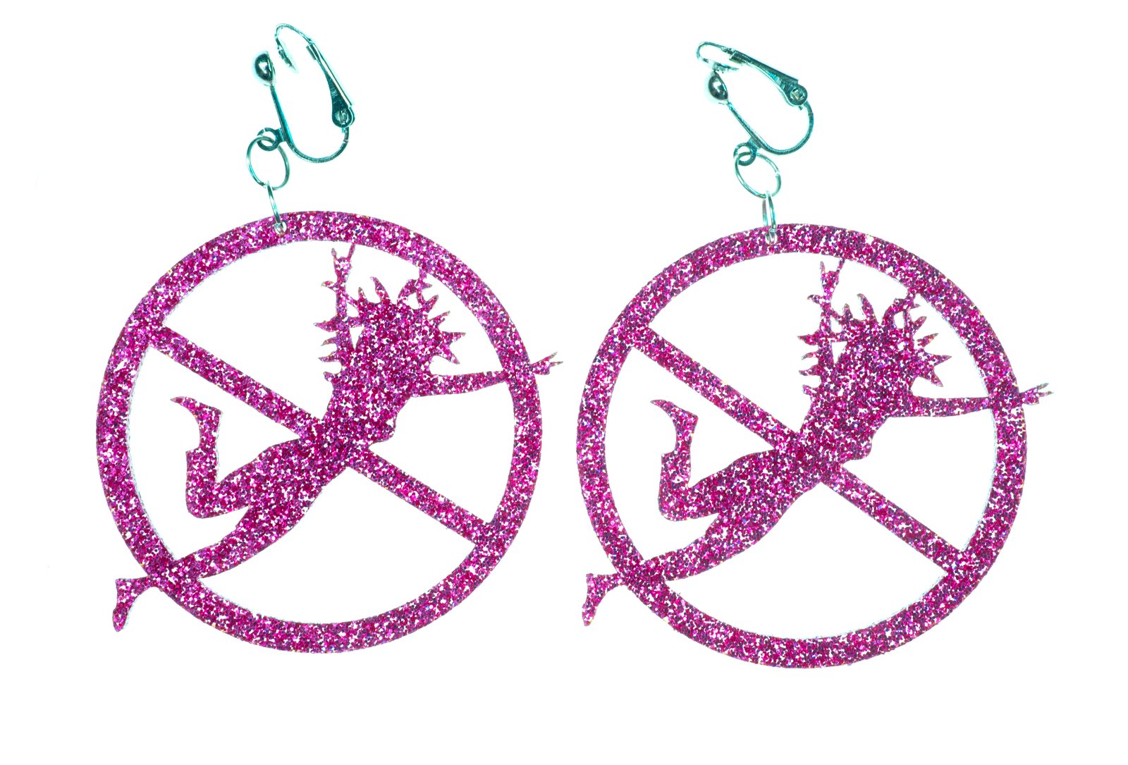
P.P.S. Claire (@LaserMistress on Mastodon) made me these super rad laser-cut acrylic clip-on earrings. You can see me wearing them on Crowd Supply’s Live from Supercon stream. I’ll see if I can convince her to somehow make these available for other people who want their own. Stickers are passé. Real hackers put earrings on their laptops.


