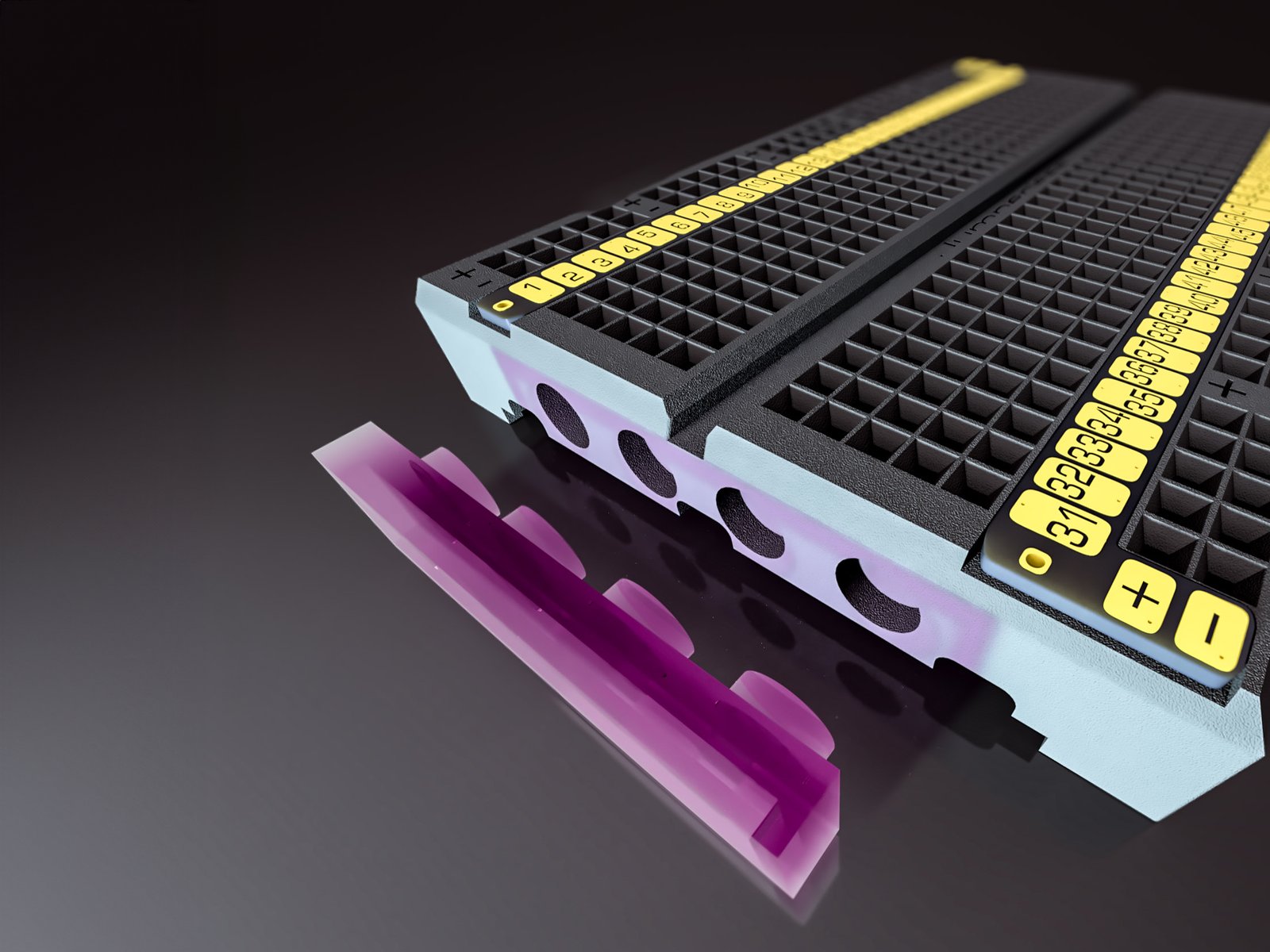
The Jumperless V5 beta units have been lovingly received by my favorite group of nerds and, of course, the first thing each of them wants to do is something I hadn’t even thought of, let alone written firmware to support. Which is exactly why these beta tests are so great.
Most of the coolest functionality of Jumperless has come from just hanging out with the community.
It usually goes something like:
User  > Hey, can Jumperless do [thing]?
Me    > No
Me    > Oh wait it totally could, hold on
         ~ a few minutes later ~
Me    > Okay open the app and let it auto-update the firmware
The most recent of these conversations happened yesterday and it resulted in an upgrade to the way Jumperless handles USB-Serial pass-through that I didn’t think was even possible, let alone something that works so nicely you simply don’t have to think about it.
Serial Passthrough
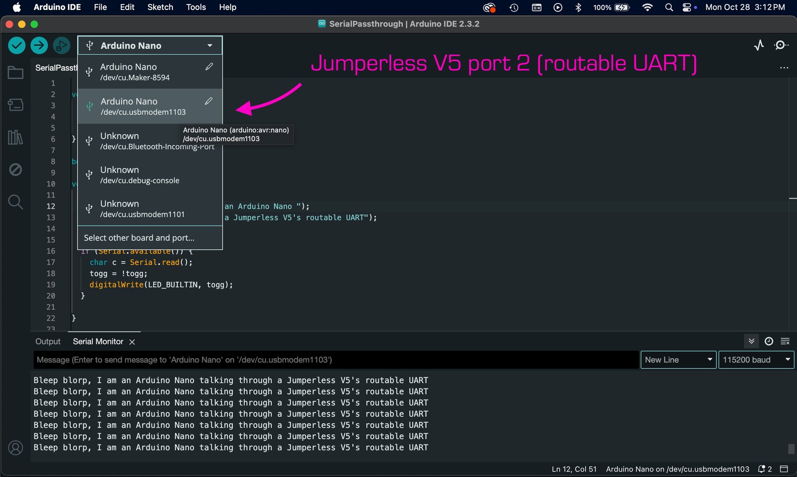
The RP2350 supports 32 USB endpoints which is USB-speak for one device showing up to your computer as if it were multiple devices, so you can talk to each of them separately. Jumperless V5 uses three of them (for now) and so appears as three separate ports: Port One speaks directly to the onboard RP2350B for making connections and generally controlling the thing, Port Two is for MicroPython REPL (I will talk about that in a future update), and Port Three is the routable UART. Anything you send to that port gets passed right through to wherever you connect your Jumperless’s Tx and Rx lines.
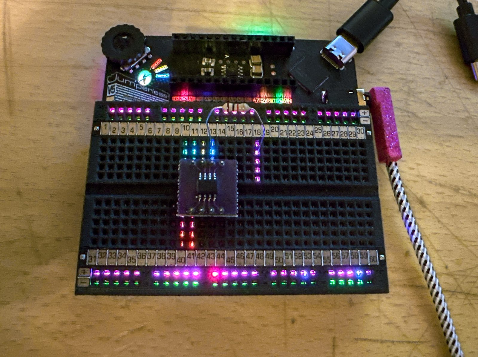
How do you hook up the routable UART lines?
Like this:
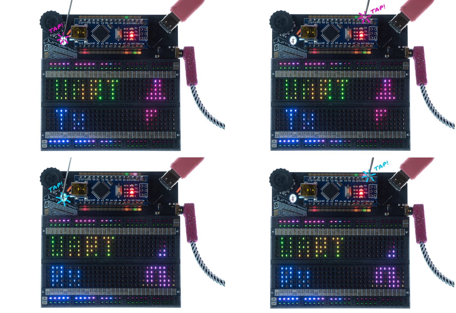
Then you can open up any IDE you like, select Jumperless V5’s third port, and it acts just like your dev board was plugged in with its own USB cable.
It even grabs the special hardware flow control signals (RTS/CTS/DTR) and does the proper things with them to trigger the reset lines. You can also attach them to a GPIO and route them anywhere to flash chips that aren’t in the Nano header.
The Ask… Or: How I Learned To Quit Worrying And Love UPDI
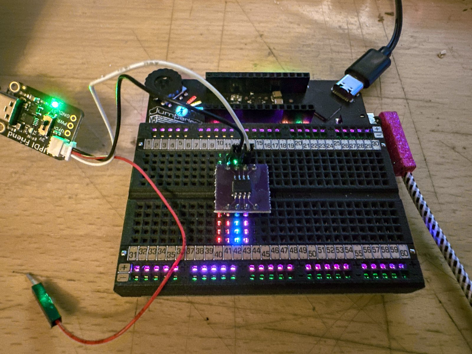
The first thing one of the beta testers wanted to do was flash an ATTiny412 with UPDI.
To program the newer AVR chips, Microchip uses a protocol called Universal Program and Debug Interface, which is really just UART (Universal Asynchronous Receiver / Transmitter) with the Tx and Rx lines connected together.
Note
I love the new AVR chips, in fact, the original proof of concept Jumperlesses (called breadWare back then) used an ATMega4809.
You can make a UPDI programmer for yourself with just a cheap USB-Serial adapter.
USB Serial Adapter
--------------------                                    To Target device
                DTR|                                  __________________
                Rx |--------------,------------------| UPDI----------------->
                Tx |-------------'          .--------| Gnd
                Vcc|---------------------------------| Vcc
                CTS|                     .`          |__________________
                Gnd|--------------------'
--------------------
It’s so simple they didn’t even need to make the guide an image, just some gloriously retro ASCII art.
Given that we can already do serial pass-through, you’d think this would just work. The tester and I were both mildly surprised when it didn’t.
So he got out a UPDI Friend and compared the output.
Here’s what the Jumperless was putting out (this wasn’t working):
And here’s the UPDI Friend’s output (this was working):
Note the one with the framing errors is the one that worked. This was extra confusing, until we thought about what "framing" actually means here.
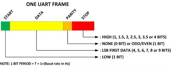
Specifically, 8N1 (8 data bits, no parity bit, 1 stop bit) is just so common for 99% of things these days that it’s easy to forget anything else is ever actually used. Even the logic analyzer forgot about it, hence the framing error.
It turns out UPDI actually uses 8E2 (8 data bits, 1 even parity bit, 2 stop bits) and, once we changed the routable UART to that, UPDI flashing through a Jumperless V5 worked like a charm.
The Part That I Didn’t Think Was Even Possible
But then, how do we let users change between different configurations/baud rates depending on what the routable UART is connected to?
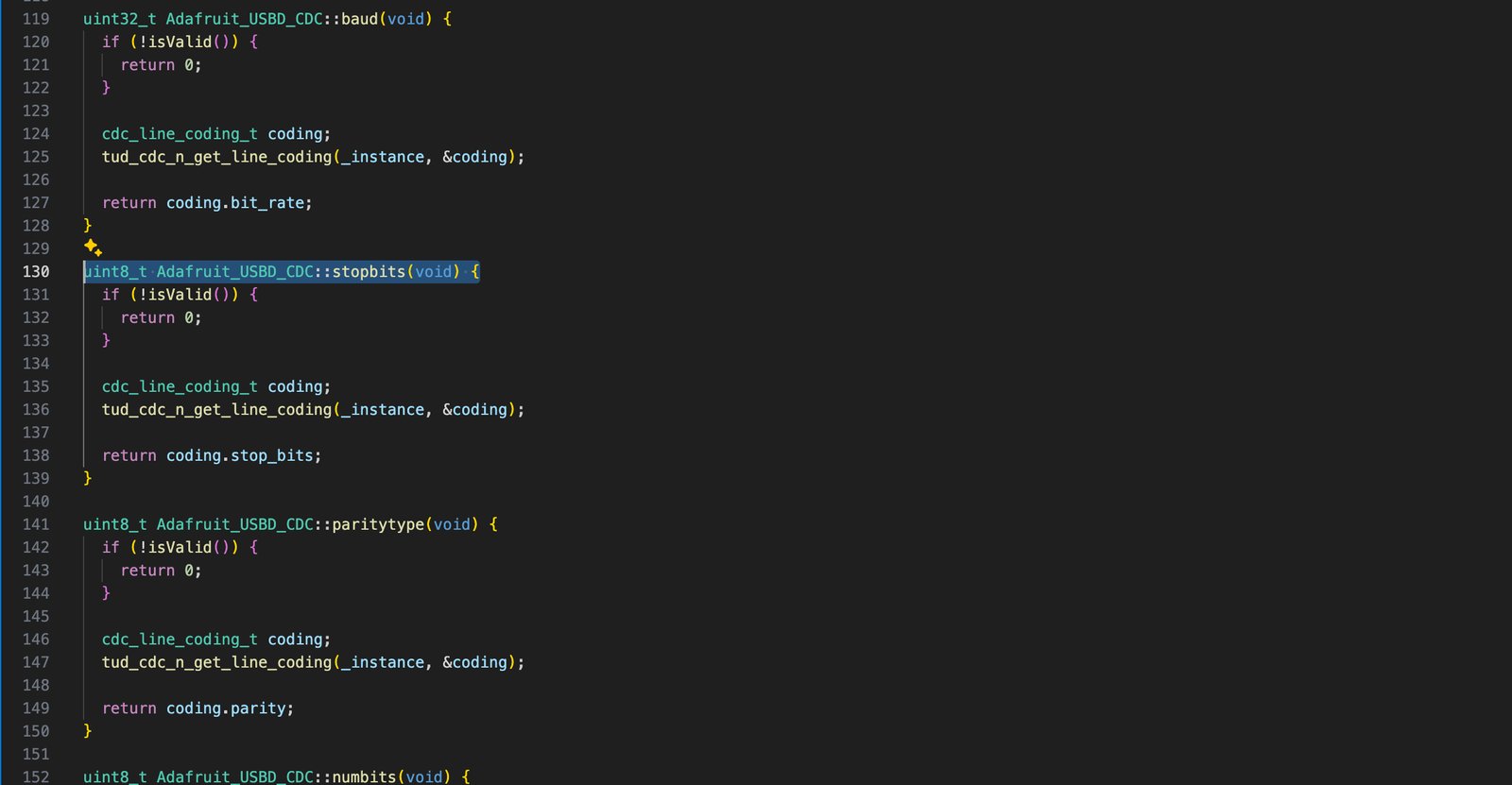
After a bunch of digging through the TinyUSB Library, I came across this:
What?! I can just straight-up ask?!
I was thinking I was going to need to write a whole thing to send test data to itself and figure out the baud rate and encoding with some hacky function, but nope, asking works. There’s a life lesson in all this, sometimes just politely asking for what you want is the right move.
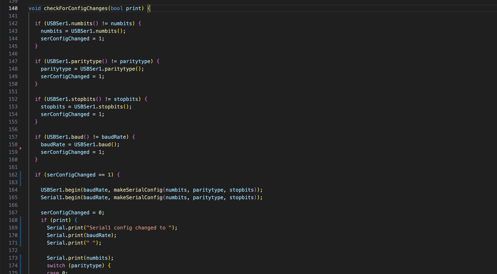
So let’s write some code that uses these magical functions to check for any config changes from the host side and then restart the pass-through side with the same settings.
Wow, this made serial pass-through soooo much less finicky. Not only for UDPI, now flashing the Arduino in the header is rock-solid too. This also lets you put an RP2040/RP2350 into boot mode with the 1200 baud "tickle" thing instead of needing to press the button.
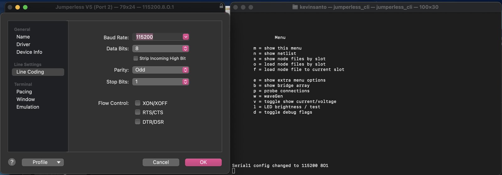
So here’s what changing the settings looks like now:
Yep, you change settings on whatever serial program you’re using and they’ll be reflected on the Jumperless. What makes this extra useful is it allows things like avrdude to do all their serial port magic without any extra setup. And it’s really cool to be able to remove menu options.
If you need any of those other flow control signals (DTR, CTS/RTS) that are sometimes used to pull the reset lines low or whatever, you can attach them to any of the routable GPIO and they’ll do what they’re told.
So there you have it folks, Jumperless V5 is now even better at being series of tubes. I’m also kind of kicking around the idea of making it a series of bricks as well…
Let me know whether or not you think this LEGO thing is a terrible idea on the Jumperless Discord, Forums, GitHub, Twitter/X, Bluesky, Mastodon, or in person at Hackaday Supercon 2024.
Love,
Kevin
P.S. Huge thanks to @DerelBims for contributing a lot of the code you see in this update!
