Project update 2 of 2
Our New Design Is Assembled!
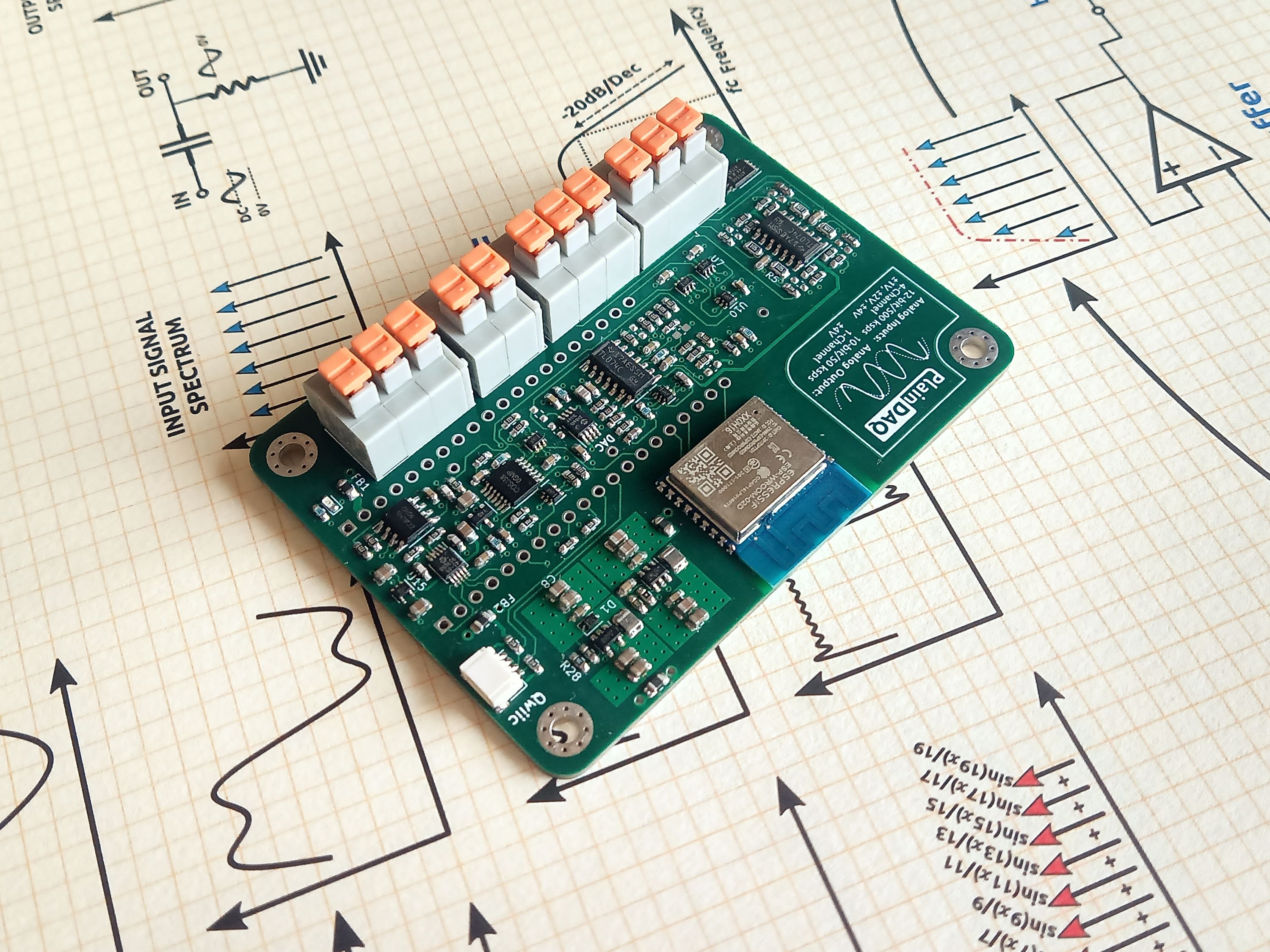
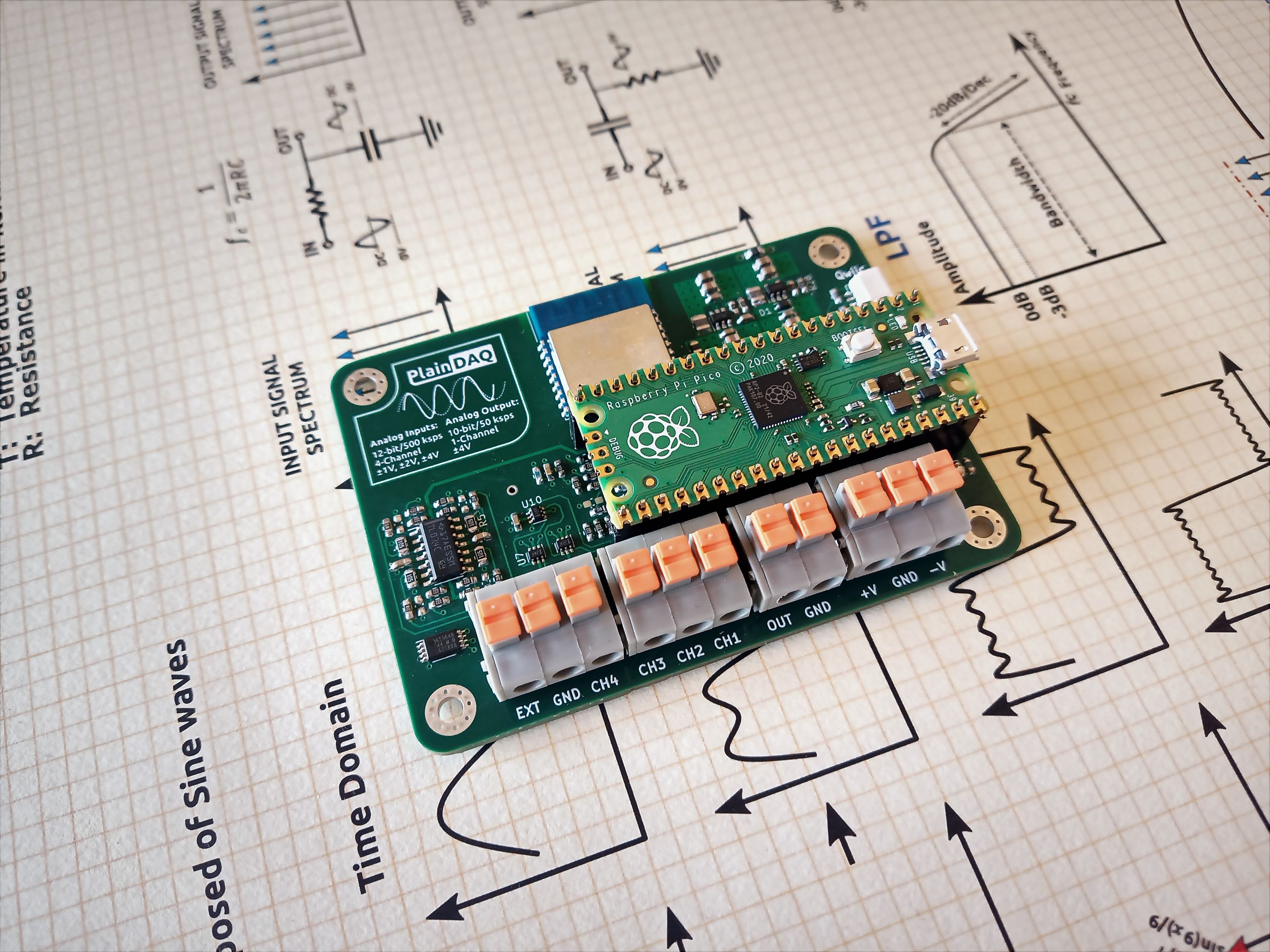
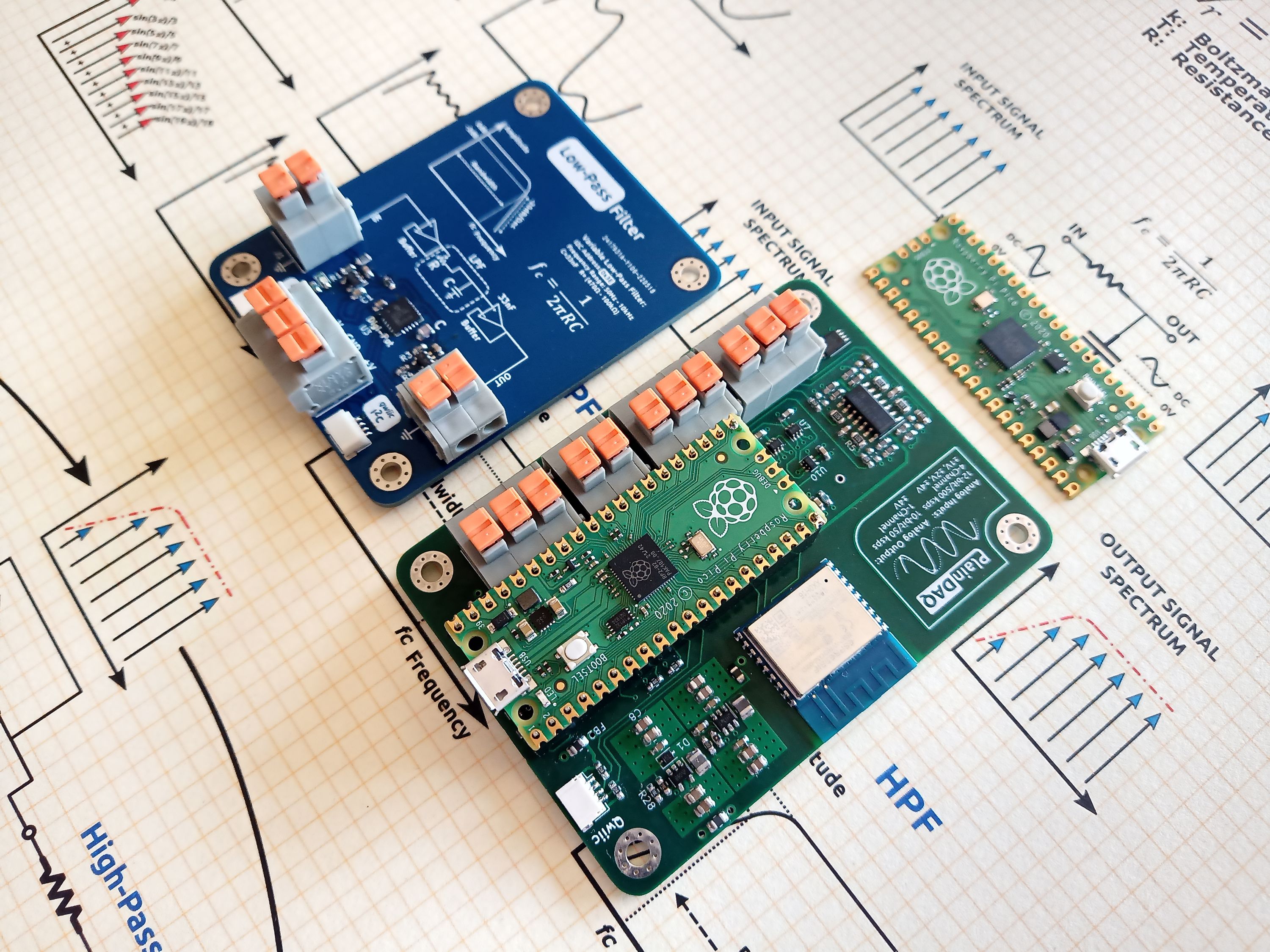
by Alperen AkküncüAfter a stupidly long delay, I finally managed to get PCBs for our new design, so I used them to assemble two boards, and I think they look great. I hope you all enjoy the new look!
Filters!
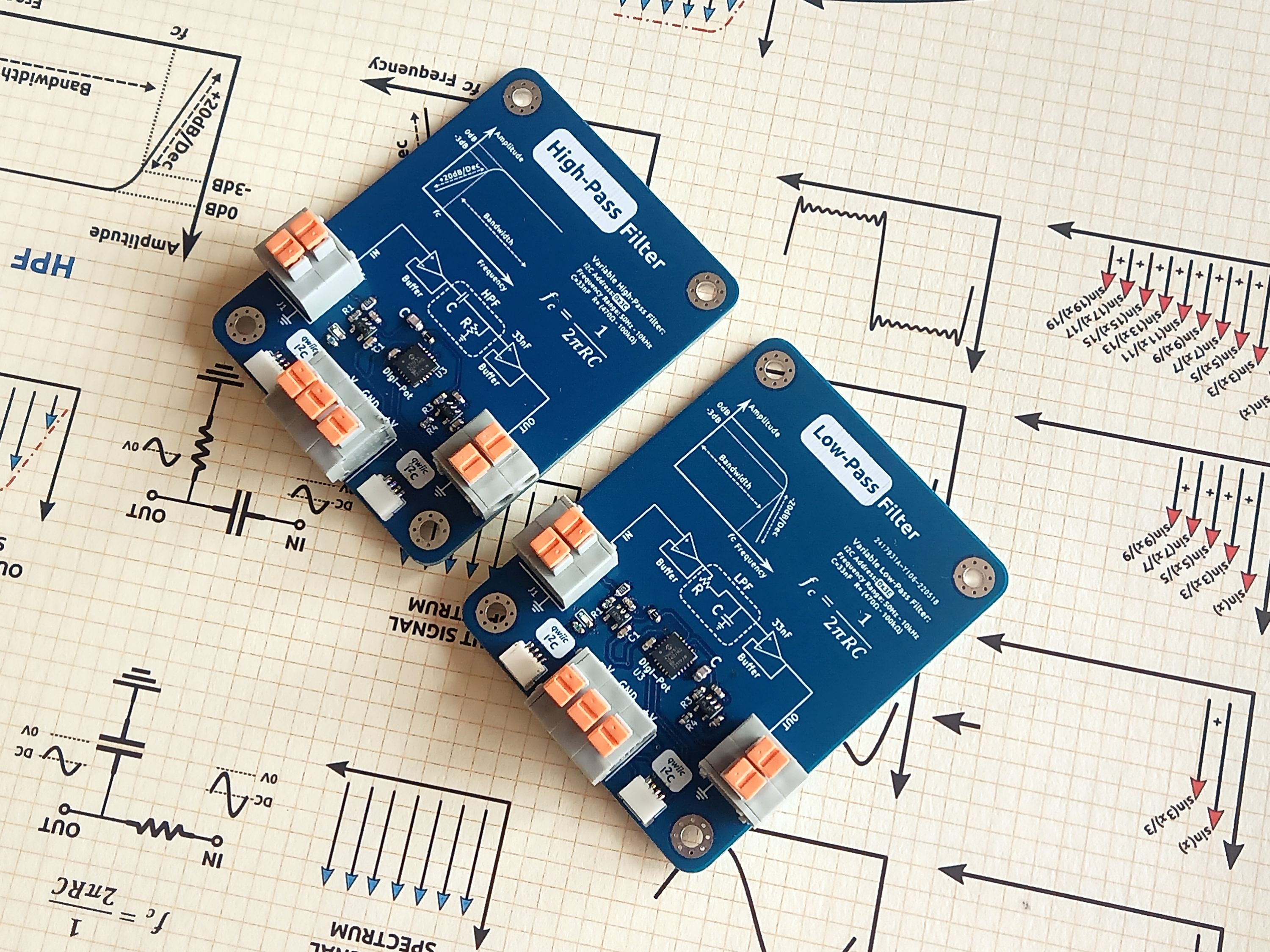
I designed low-pass (LPF) and high-pass (HPF) filters to be used with PlainDAQ. And these are no ordinary filters! They are controllable over I²C, you can set their cut-off frequencies, and you can cascade them to create different filters such as band-pass and band-stop filters. Here they are:
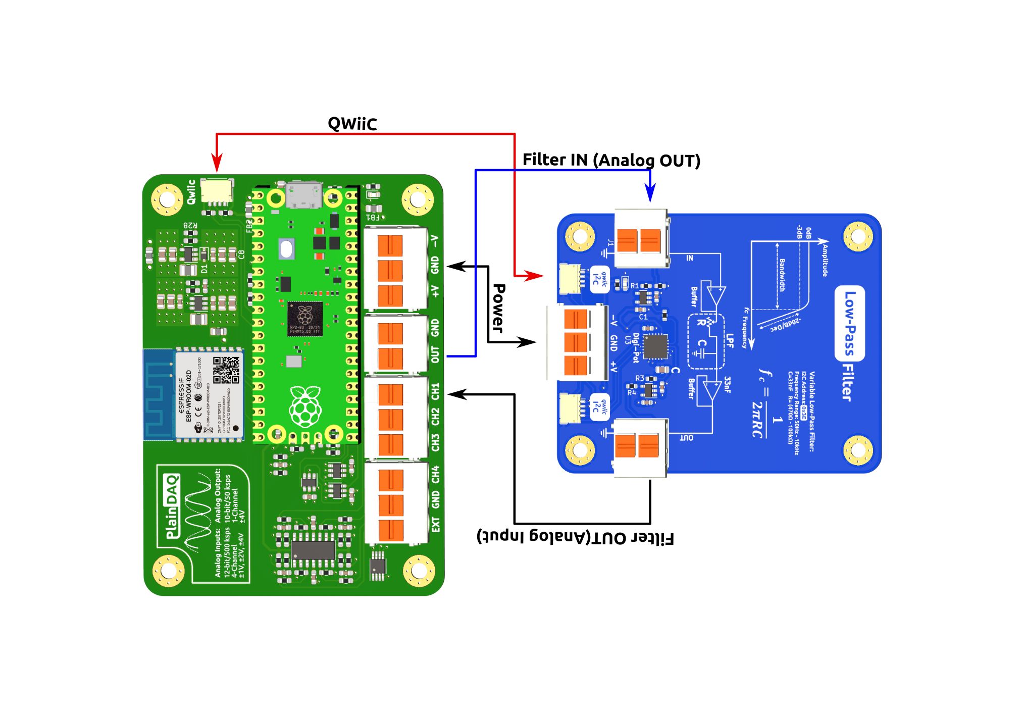
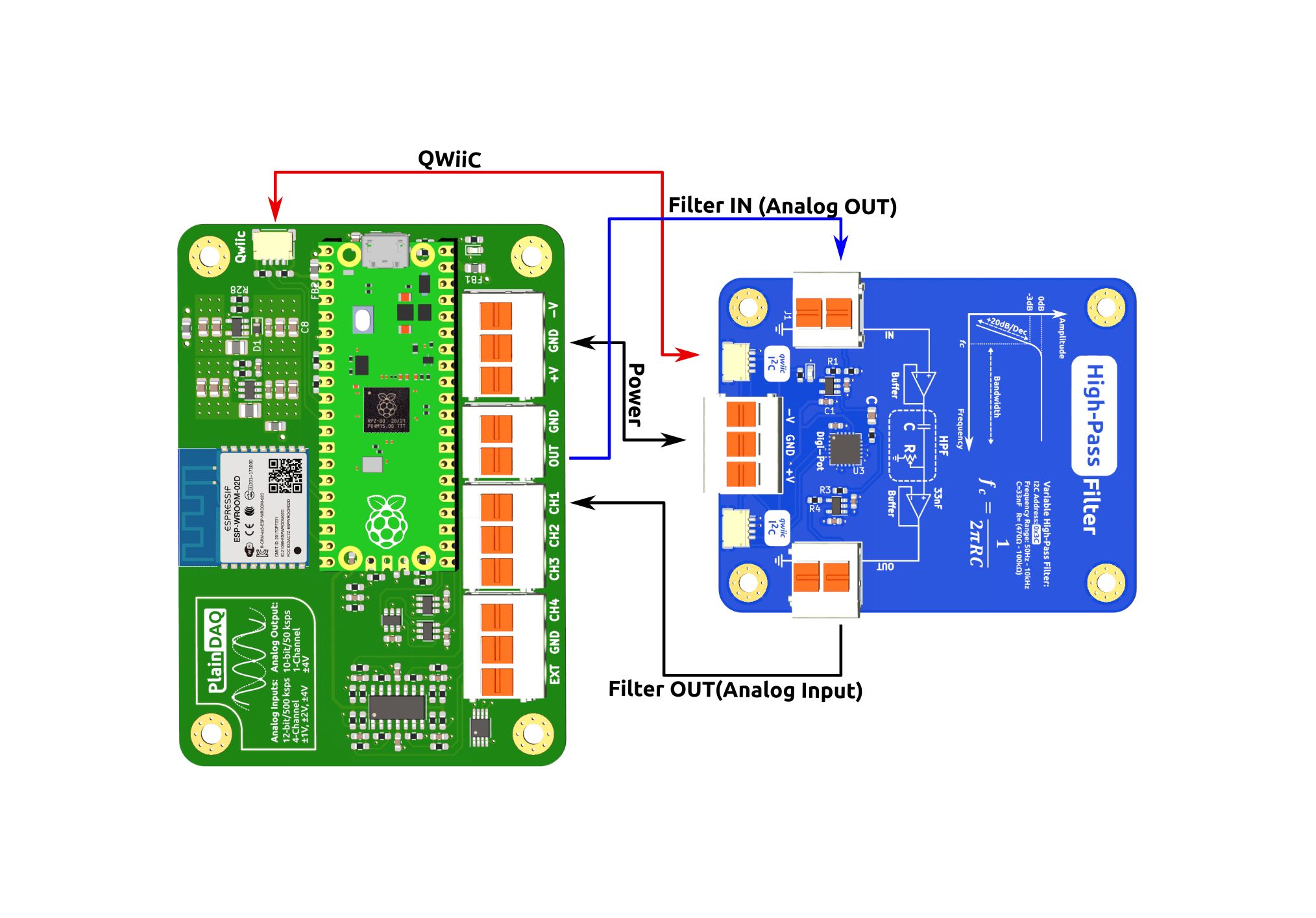
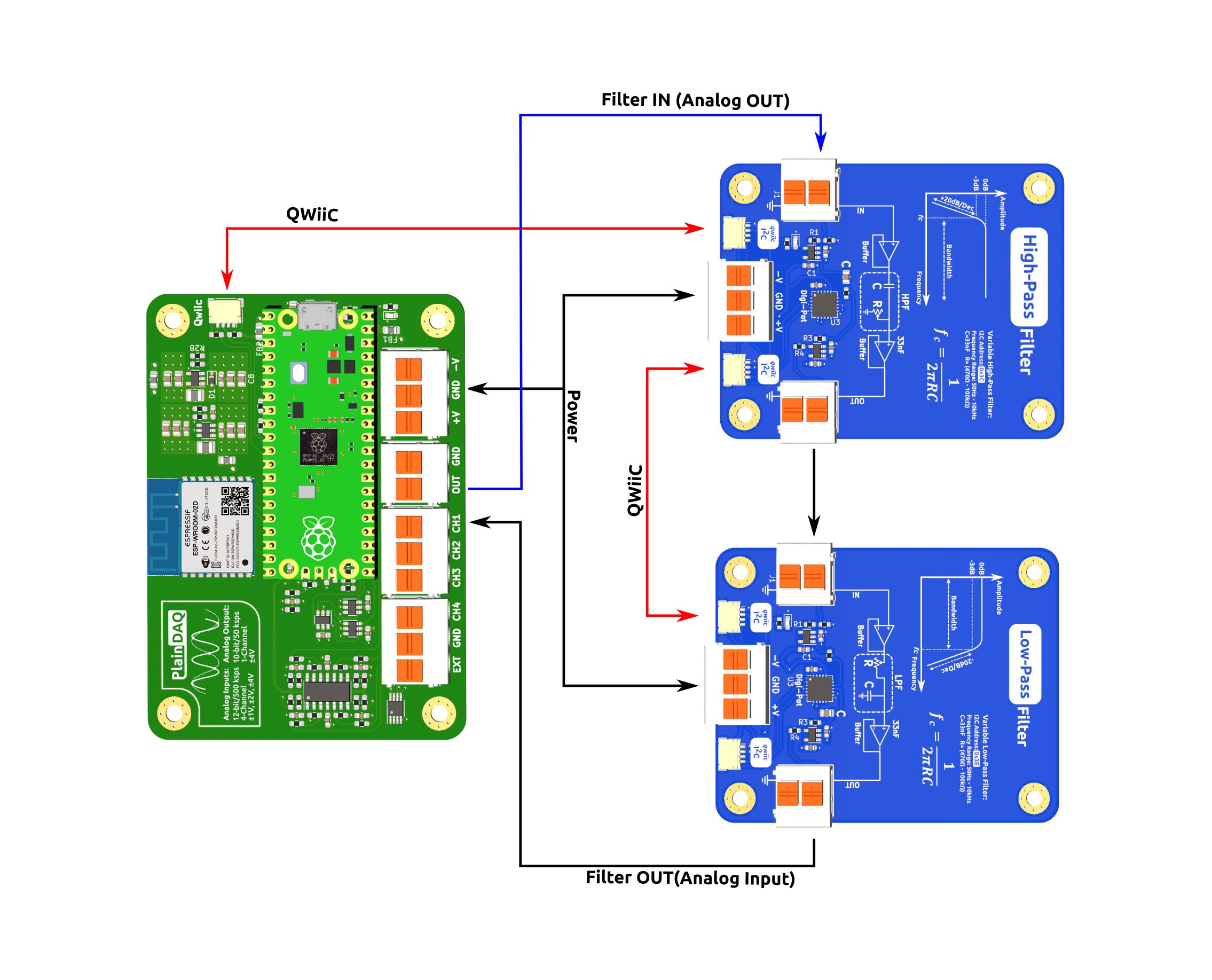
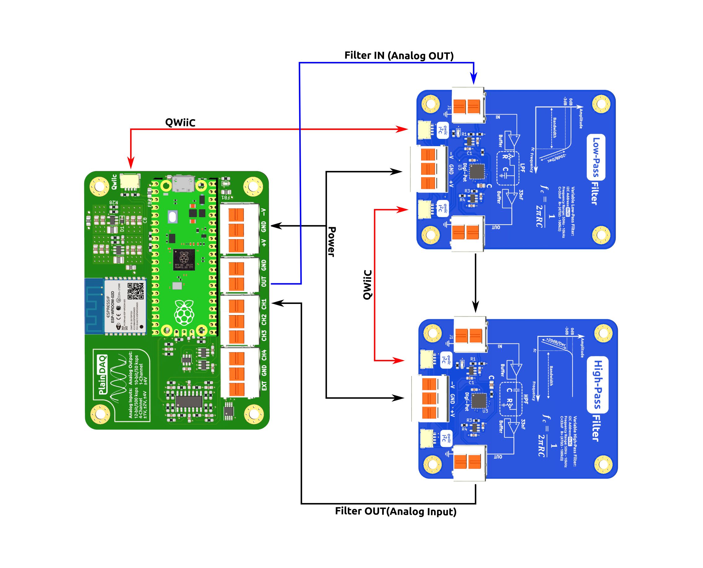
I also prepared some diagrams to help explain how each configuration can be used with PlainDAQ. There are four configurations: low-pass, high-pass, band-stop, and band-pass:
Low-Pass
High-Pass
Band-Pass
Band-Stop
Board-Layout Diagrams
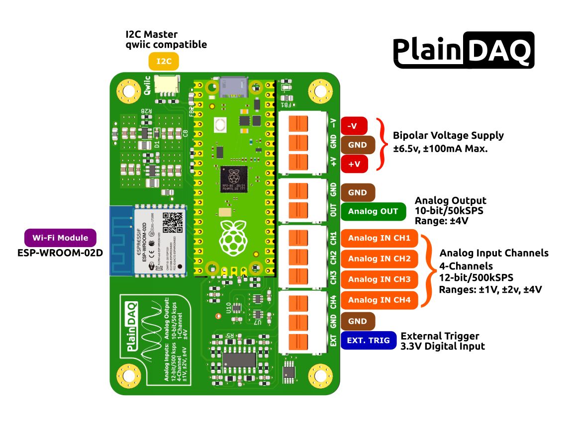
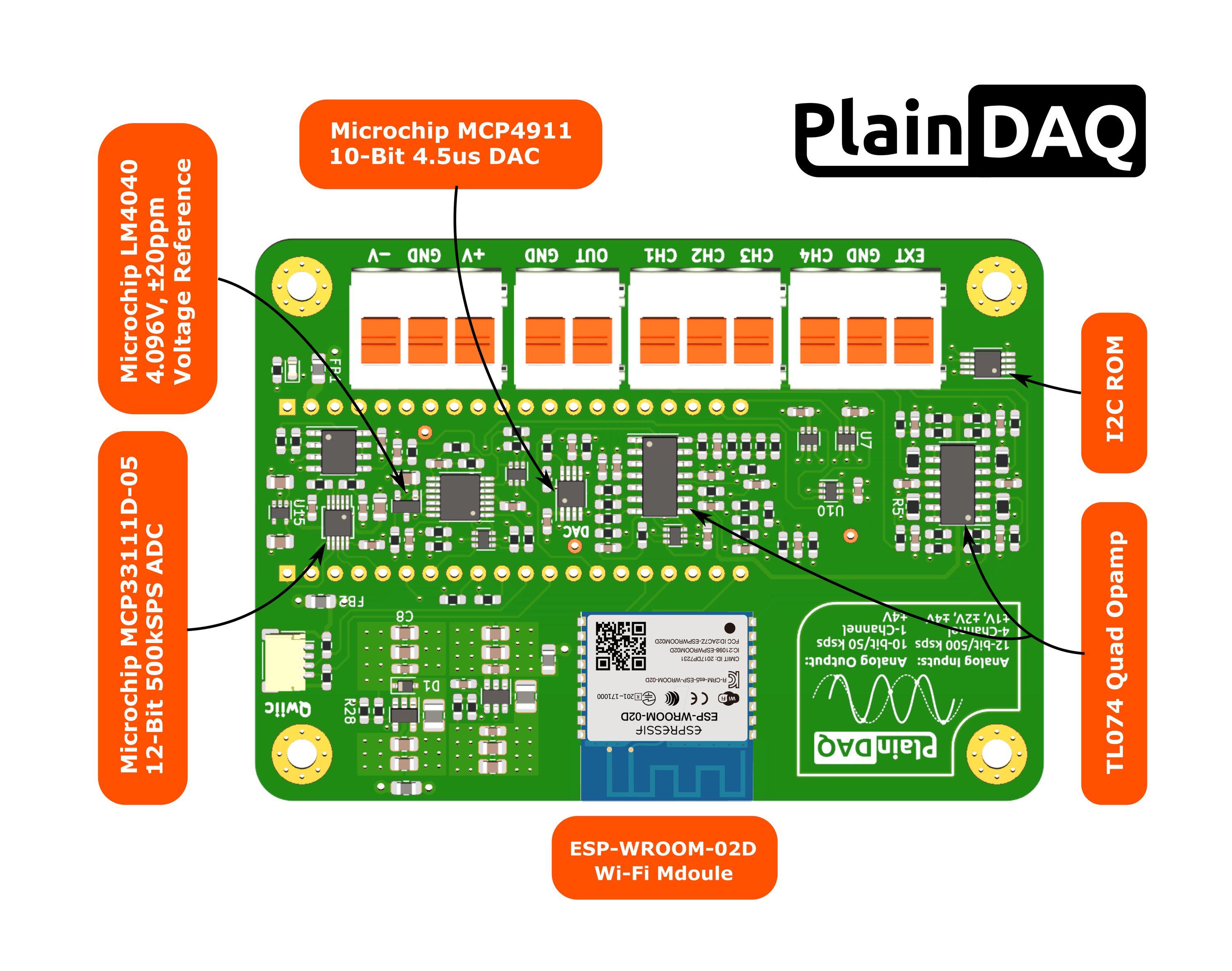
I see a lot of open-source dev boards with cute little diagrams that identify key components, pinouts, connectors, etc. I thought to myself, what’s keeping me from having one of those!? So I designed the following. I hope you find them useful!
Refining the Bill of Materials
Finally, while working on the above, I also spent some time cost optimizing the PlainDAQ BOM. I’m doing my best to build something that anyone can afford.
Stay Tuned
That’s it for today. I had hoped to start picking up speed sooner, but I’ve had to focus on my day job lately. So thank you for your patience. And rest assured, I’ll never stop developing PlainDAQ! Sooner or later, we’ll get this campaign launched, and it’s going to be great.
Meanwhile, I try to share my progress via Twitter. If you’re curious, you can follow me there as well.


