Project update 10 of 23
January Update
by KrakenRF IncWe hope everyone has had a great new year and holiday season! In this update we’ll show some new examples of the KrakenSDR in action, and some updates on software and manufacturing.
Beacon Tracking Experiment
We recently performed an experiment where we placed a low-power license free 434 MHz beacon on a vehicle and drove around the neighborhood to see how well the KrakenSDR could track it. A continuous signal as well as a pulsed signal with 100 ms pulse duration every 3 s were tested. The beacon antenna was mounted on the roof and was configured for a maximum legal output EIRP of 14 dBm (transmitted with 12 dBm (16 mW) power and a <2 dBi antenna). The KrakenSDR antennas had moderately clean line of sight to the vehicle for most of the journey, although often obscured slightly by terrain, houses and other vehicles.
The video below shows a demonstration of the results, where the moving blue dot is the vehicle with the beacon, and the bearing line points from the fixed receiver to the vehicle. Better results are obtained when the transmitter has clearer line of sight to the receive antenna, but even without a perfect line of sight, it still tracks the signal with some multipath error. It’s worth pointing out that sometimes when larger vehicles, and especially trucks, pass or stop next to our vehicle at a light, the signal direction becomes more distorted than usual, and this can also be observed at some points in the video.
New Passive Radar Code
Our standard 2-channel passive radar code is now ready for testing and the open source code is available on GitHub at https://github.com/krakenrf/krakensdr_pr/tree/development
Tests with the new Passive Radar code have shown that we can achieve observation integration periods of up to 2^22 samples at 2.56 MHz bandwidth (~1.6 s integration time) with acceptable refresh rates on the Raspberry Pi 4 (bounded by CPU power). We also tested on a 6-year old laptop/tablet hybrid running Ubuntu. Although this laptop has a relatively underpowered 2-Core Intel i7-7Y75 mobile CPU we found good results with the computation time being only slightly slower than the integration time. It seems that any modern desktop PC running Linux will be able to run the passive radar code at full speed.
We’re also actively investigating if we can get some sort of improvement on the Raspberry Pi 4 through the use of the Pi 4 Videocore VI GPU via Vulkan and Vulkan FFT libraries.
There have been some questions about range resolution. If you use a wide-band illuminating signal, such as DVB-T we can utilize the maximum available bandwidth of 2.56 MHz which yields us a bistatic range resolution of about 58 meters (range resolution = c/2B, C=speed of light, B = bandwidth). This means that two objects spaced 58 meters apart can be resolved into individual cells on the range-Doppler graph. And obviously larger objects will give stronger returns compared with smaller objects, so larger objects in the same range cells will dominate. We aim in the future to investigate whether it’s possible to combine data from more channels to double the bandwidth which would yield us even better range resolution. Of course if the two objects are moving at different velocities, the Doppler shift’s will be different too, which could allow the system to resolve both objects in different Doppler cells. Increasing the observation integration time improves on Doppler resolution (and SNR), but could also result in the detection being spread over multiple range cells.
The video below shows a time-lapse example of the new passive radar code in action, with a 2^21 sample integration period used. This results in an 800 ms integration time, and about a 1.2 s refresh rate on our low power laptop. The video is sped up 40x and ADS-B data is shown next to the passive radar range-Doppler graph for reference.
Kerberos/Kraken Beta SD Card Image
We have now released the second iteration of the SD card beta image which now includes updated direction finding code and has the 2-channel passive radar software preinstalled on it too. Instructions on where to download and how to setup the SD Card image can be found on the krakensdr_doa and krakensdr_pr GitHub Readme pages.
The direction finding code now optionally supports the use of the third party KerberosSDR switches created and sold by Lakshore Labs (Corey K) on Tindie. It will support other similar switches too. If connected to the Raspberry Pi GPIO as described in the instructions for the switches, the code will automatically switch in and out the antennas when calibrating with the noise source, allowing a KerberosSDR to approach KrakenSDR automatic calibration functionality. The current SD card image has this functionality enabled by default.
Links to the image file and instructions can be found on the krakensdr_doa and krakensdr_pr GitHub pages.
Arrow Antennas Release their Kraken 5-Element Array
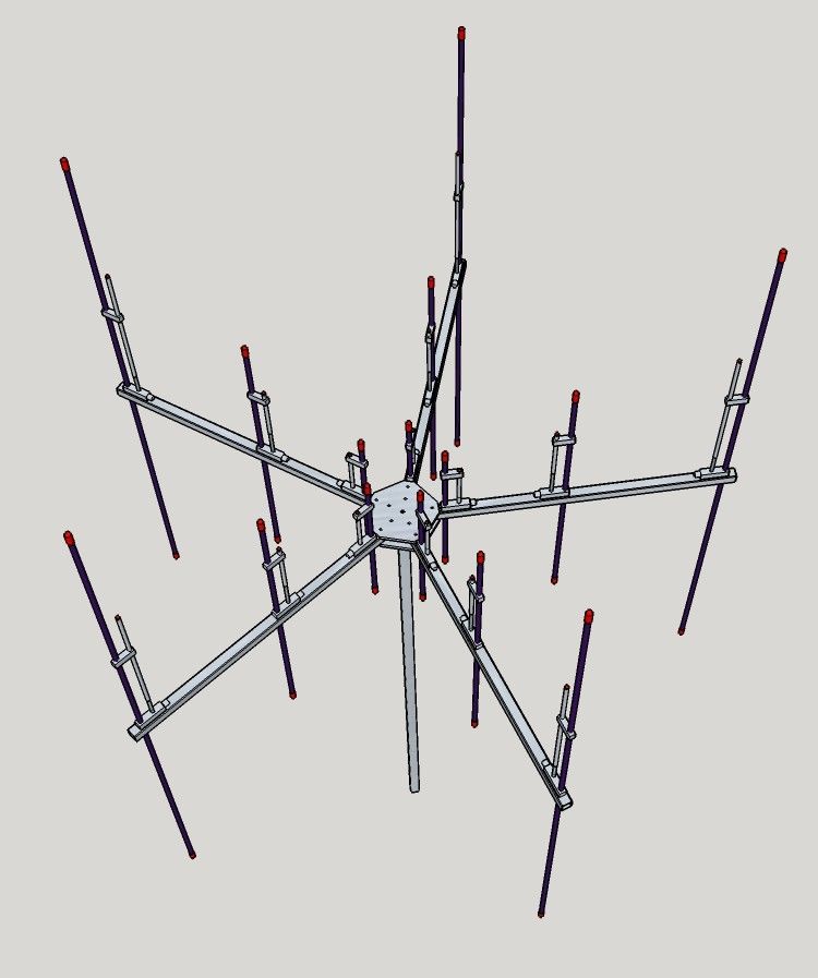
Earlier on in the campaign we noted that we were collaborating with third party company Arrow Antennas who were creating a 5-element dipole antenna array for use with fixed site KrakenSDR direction finding applications. Unfortunately shortly after we announced that we were informed that there was an aluminum shortage, and so the release of the antenna would be delayed. However, we’re now happy to announce that this constraint has been overcome, and they have now released the antenna for sale at http://www.arrowantennas.com/arrowii/krsdr.html
If you’re ordering these antennas, you’ll need to order one array, (either the large or small array depending on what frequencies you’re interested in), and at least one set of 5-dipoles for the frequencies you are interested in. You’ll also want to order a set of 5 of their BNC to SMA cables.
We note that their rendering shows multiple elements on the same arm, however in reality you will only be able to use one set of elements on an arm at a time. When multiple elements are used on the same arm we see that the signal’s angle of arrival gets distorted by reflections and refractions caused by the unused elements.
Manufacturing Updates
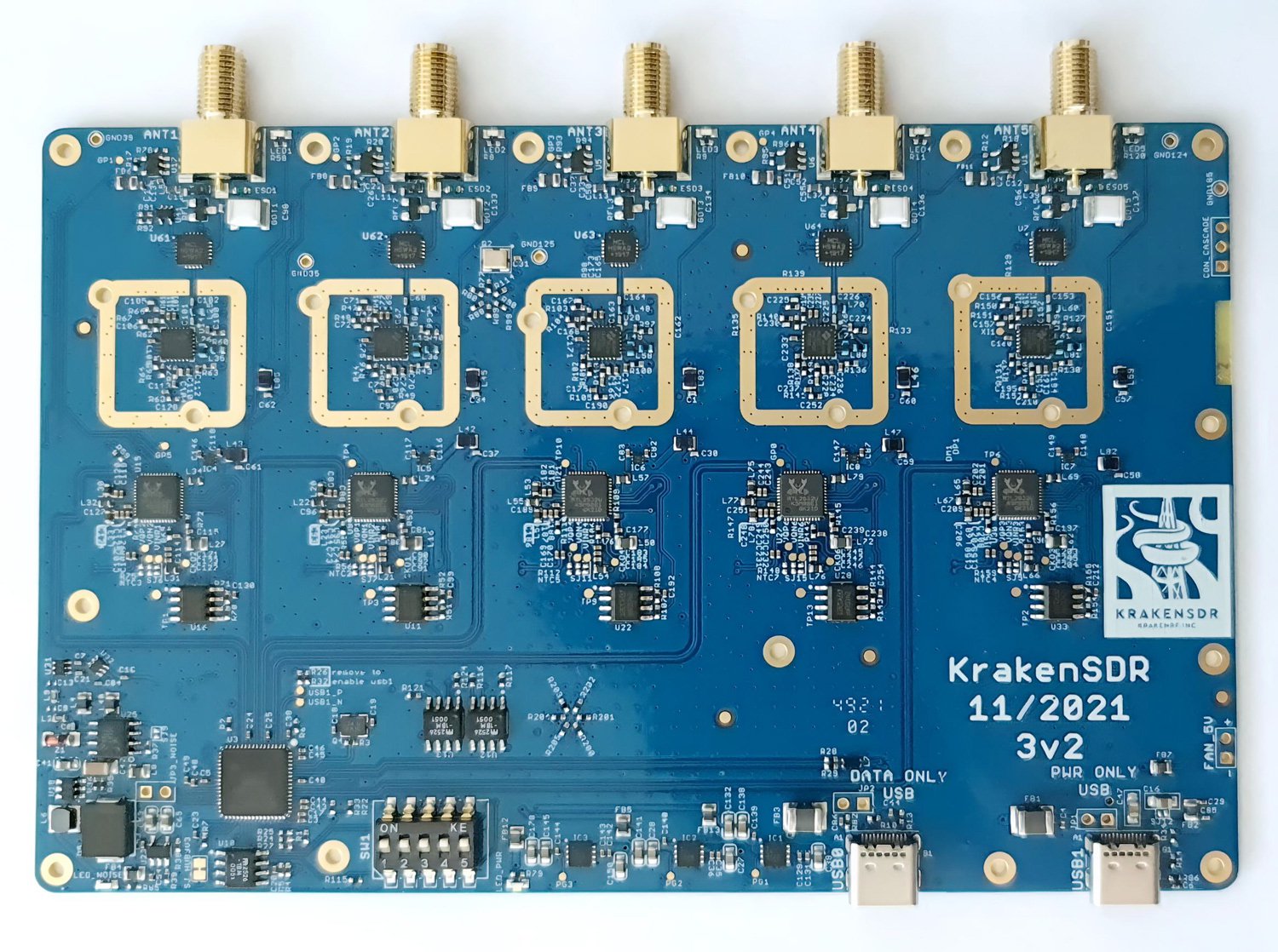
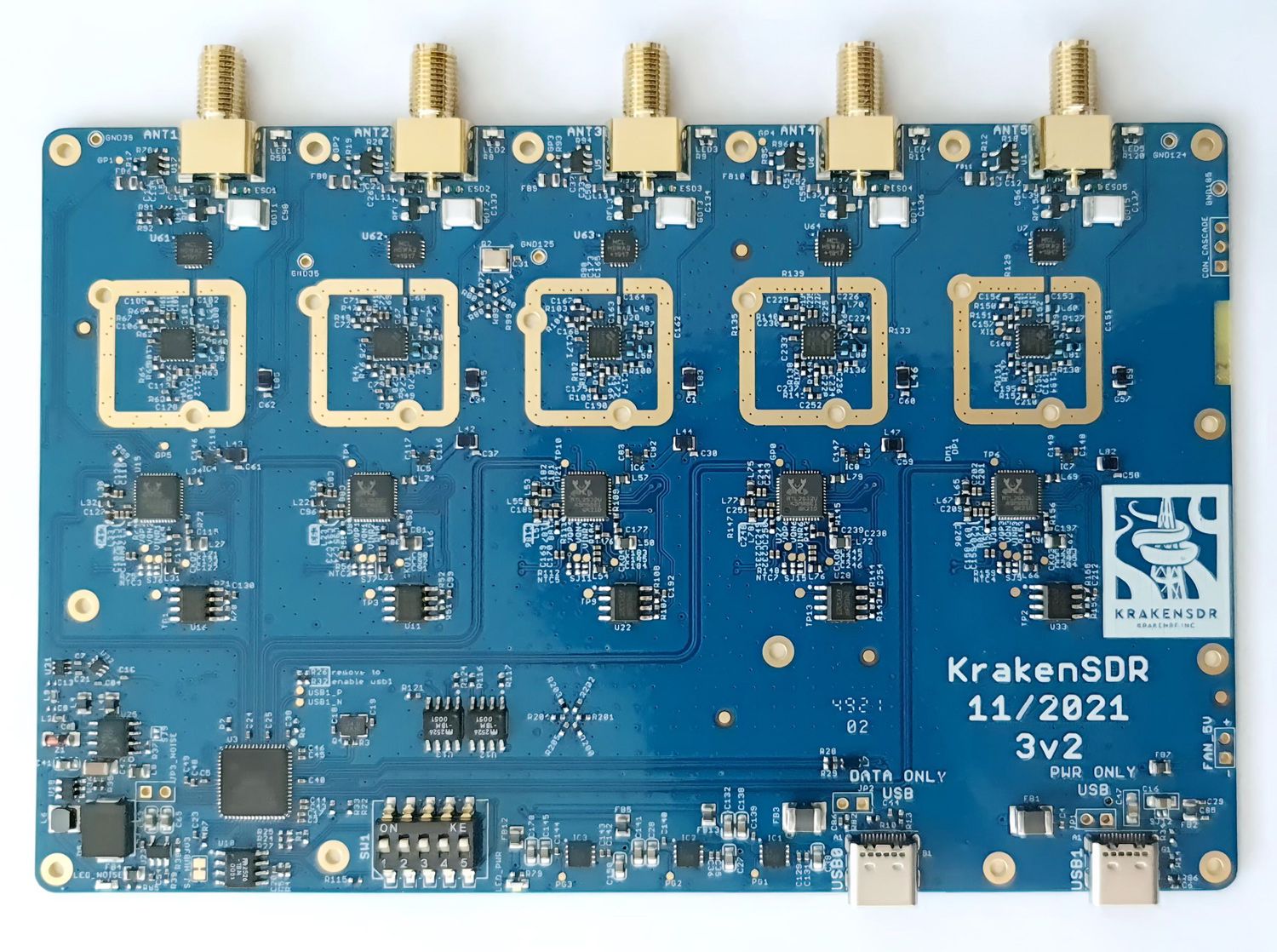
A few days ago we received the final batch of prototypes from the factory and in our testing they have been running perfectly and we find no remaining issues to resolve. The custom SMT SMA’s that we mentioned in the last update work well and fit just fine as expected. At this stage the PCB prototyping is complete, and we have booked in our production of the first batch of 1000 PCBs which we expect to begin shortly after the Chinese New Year (CNY) holidays. We also plan to have our CE/FCC EMC and RoHs compliance testing completed in an expedited manner after CNY as well before mass production gets underway.
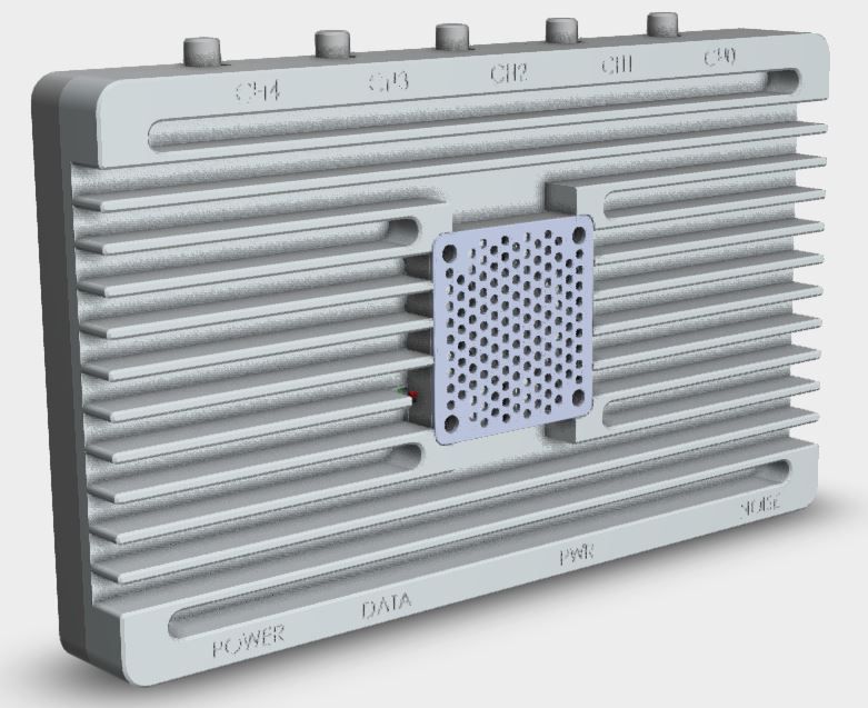
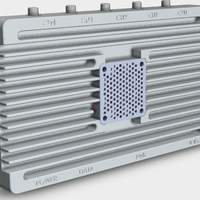
The enclosure redesign that now adds active fan cooling is also now complete. A prototype of the latest enclosure is booked to be cut soon and we will have updated pictures in a few weeks and we have already ordered the fans we plan to use.

