Jie Zou
Video & Cameras
FPGA Boards
Jie Zou
Video & Cameras
FPGA Boards
RggBer is FPGA-based, open video development hardware aimed at bettering the lives of professional video application or hardware developers, engineering students, and video producers and creators. Basically, RggBer captures, processes, and distributes digital video signals in multiple combinations and formats. With RggBer, video developers are spared from having to design, build, and program basic video processing hardware, freeing them to work on the new and interesting parts of their projects. For maximum flexibility, RggBer has a small form factor and multiple input and output options. You can even connect multiple RggBers to create multi-camera networks. RggBer is the Swiss Army Knife of digital video processing.
RggBer is based on an FPGA so it is fully programmable and configurable. The FPGA’s parallel data processing capability and flexible structure lets users experiment and innovate to their heart’s content.
RggBer was conceived in the aftermath of a project that was intended to create a basic image-capture device for microscopy. The team working on the project spent far too many development cycles on low-level things like PCBA design, FPGA programming, and firmware design and testing. After churning through all that, the team had precious little time left for developing the key features of the project. This led to the team to wonder, “Is it possible to create a standard hardware platform for digital image and video development? Can we free designers from spending time on general, repetitive basics?” The answer to those questions is RggBer.
The use cases for RggBer are nearly limitless, but here are a few of the user groups who can benefit from it.
For all of these users, RggBer helps by taking away the time-consuming drudgery of building up basic hardware and/or programming a complex FPGA. It provides a common platform for testing and sharing work.
In order to be as flexible and useful as possible to as many kinds of users as possible, we came up with a set of criteria that RggBer had to meet. We determined that Rggber must be:
The board level I/O diagram below shows how we’ve implemented these design criteria.
RggBer is a true multi-functional tool, its uses span a broad spectrum of interests and industries. Here are just a few possible applications:
As the campaign progresses, we’ll provide updates illustrating some of these applications in greater detail.
In applications such as a security camera, RggBer may need to be installed in a remote location, requiring some form of remote control. We have developed an Android app for this purpose which can control RggBer remotely via the Bluetooth channel. The app’s source code is freely available, and it supports multi-device connections and full duplex communications.
RggBer’s design and specifications are open and available for inspection.
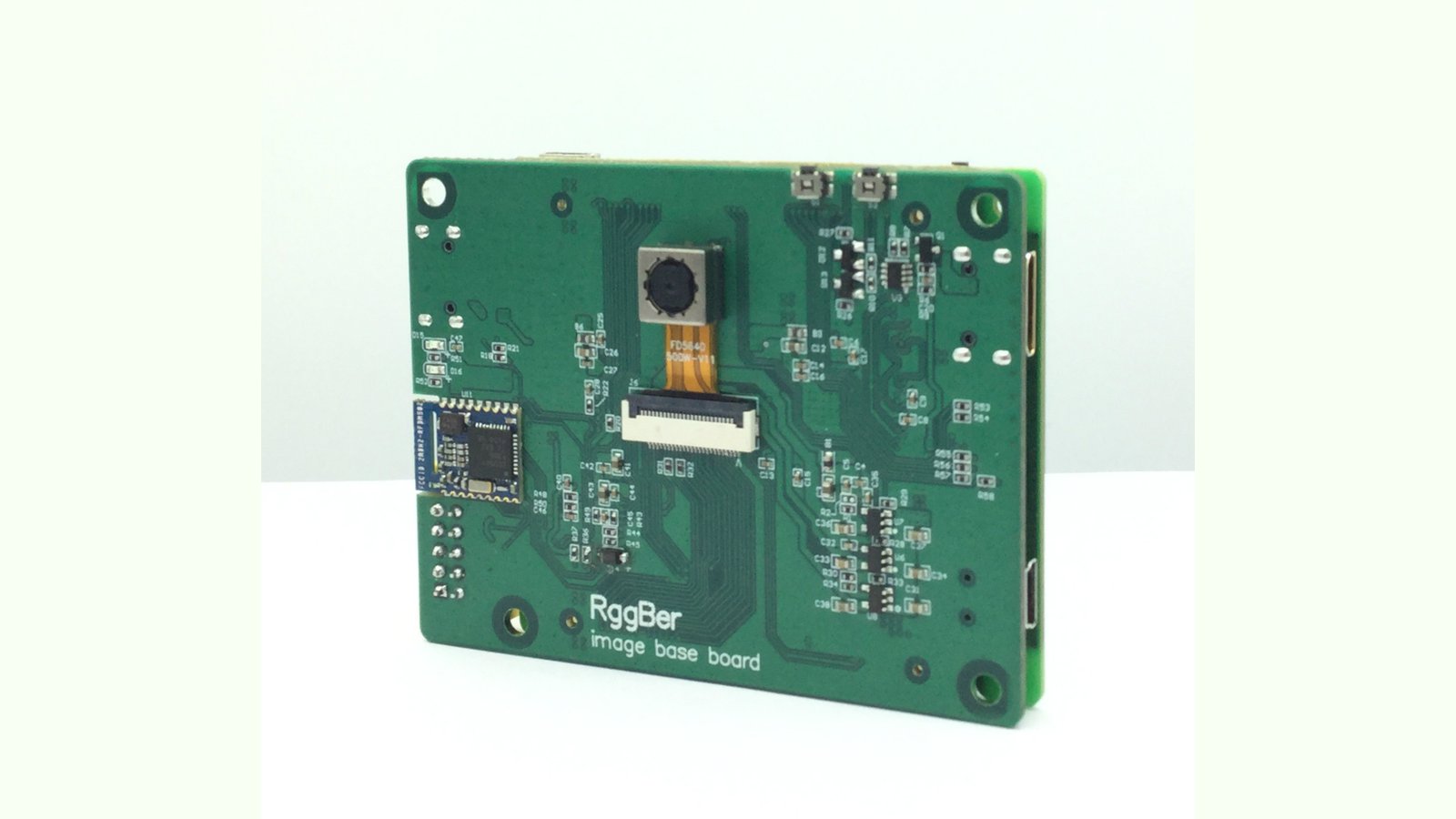
RggBer consists of an FPGA core board connected to an imaging base-board. Two specially designed interfaces handle video I/O: iXCis is a standard DVP bus while iXHis provides a high-speed LVDS bus. We are developing a variety of daughterboards with different imaging modules and sensors for these busses. RggBer also provides multiple connection options, including USB, HDMI, SD Card and Bluetooth.
RggBer’s dual board design has several advantages:
The FPGA core-board has six layers for better SI and PI performance. The imaging base-board is a four-layer design.
The FPGA core-board connects to the imaging base-board via two high-speed, board-to-board connectors. It provides user I/O to the FPGA, PLL clock outputs, and dedicated global clock inputs for future expansions.
| Key | |||
|---|---|---|---|
| A: Board-to-board connector (female) | B: USB 2.0, +5 V | C: FPGA JTAG interface | D: iXHis interface |
| E: FPGA chip | F: DDR2 chip | G: HDMI output, type C | H: iXCtrl interface |
| I: MCU C2 interface | J: MCU chip | K: HDMI TX chip | L: board-to-board connector (male) |
| M: HDMI input, type C | N: SD card interface | O: HDMI RX chip | P: mini-USB, +5 V |
| Q: BL 4.0 module | R: iXCIS interface |
RggBer provides three I/O interfaces: iXHis, iXCIS and iXCtrl. You can use them to expand RggBer’s application support and functionality.
iXHis is the interface that supports high speed channels. It uses a 50-pin FFC connector to easily connect to a USB3.0 bridge chip, an ultra high-speed image sensor, a second channel HDMI receiver, Gige PHY chip and camera-link, etc.
iXCIS is the interface that supports a standard DVP port. Via this 24 pin FFC connector, RggBer can connect to various mainstream image sensors and ISP chips.
iXCtrl is a 10-pin FFC connector that provides basic control capabilities, such as LED control, temperature control, and other PWM based controls. This allows RggBer to work in stand-alone machine vision applications.
| Interfaces | |
|---|---|
| Power Input | DC +5 V, mini-USB |
| HDMI Input | HDMI type C, 19 pins |
| HDMI Output | HDMI type C, 19 pins |
| iXCIS | Standard DVP, including 8bits data, pixel clock, CIS clock, I2C bus, Vsync, Hsync and control signals. DC+3.0 V, +1.5 V, +2.8 V and +3.3 V |
| iXHis | LVDS mode: up to 840 Mbps (TX) and 875 Mbps (RX). 15 x LVDS, 1 x LVDS clock input and 1 x single-ended I/O. Single-ended mode: 31 x single ended I/O, 2 x single ended clock input. DC+5.0 V output |
| iXCtrl | I/O: 2 channels of PWM up to 16-bit width pulse. Supports capture mode,etc. Output: 2 channels of 12bits DAC. Input: 2 channels of 12 bits ADCs up to 200 ksps. Output DC+5 V |
| USB 2.0 | Standard USB 2.0 to UART with connection to FPGA |
| JTAG | For FPGA debugging |
| C2 | For MCU debugging |
| SD Card | Standard SD card slot |
| B2B Interface | 2 x high speed board to board connector, 0.8mm pitch, 100 pins per |
| Press Keys | 1 x key for FPGA reset, 2 x keys for general purpose |
| LEDs | 2 x LEDs for bluetooth connection, 4 x LEDs for general purpose |
| Wireless Connectivity | |
|---|---|
| BT | Bluetooth to UART module with connection to MCU |
| App support | Android |
| Dimensions | |
|---|---|
| Image base-board | 78 mm x 60 mm |
| FPGA core-board | 68 mm x 60 mm |
| Main Chipset | ||||
|---|---|---|---|---|
| FPGA | 28848 LEs, 594 Kbs embedded memory, 66 18 x18 multipliers, 4 PLLs, supports DDR2 up to 200 Mhz | Frame buffer | DDR2, 2 Gbits, 2 chips x 16 bits x 64 M x 400 Mhz, up to 12 Gbps | |
| MCU | 32 K flash, (2 K+256) sram, 50 Mhz, 12 bits ADC, 12 bits DAC | |||
| HDMI TX | Video only, pixel rate 165 Mhz, 1080p and WUXGA at 60 Hz, RGB 24 bits | |||
| HDMI RX | Video only, pixel rate 165 Mhz, 1080p and WUXGA at 60 Hz, RGB 24 bits | |||
| Image sensor | OV5640 chip, 2592 x 1944@15 fps, 1080p@30 fps, 1.4 μm x 1.4 μm, supports AF, AEC, AWB. View angle 60°. VCM driven lens |
Compared to other solutions, RggBer is less expensive, smaller, and, most importantly, provides technical capabilities other tools don’t.
| RggBer | Zedboard | Altera DE2-115 | Altera C3H | Altera DE1 | Altera DE0 | |
|---|---|---|---|---|---|---|
| FPGA chip | EP4CE30F23C6 | Zynq-7000 SoC | EP4CE115 | EP3C120F780 | Cyclone II 2C20 | Cyclone III 3C16 |
| Frame buffer | DDR2, 256 MB | DDR3, 512 MB [1] | SDRAM,32 M x 32bits | DDR2, 256 MB | SDRAM, 1 M x 4 x 16 bits | SDRAM, 1 M x 4 x 16 bits |
| HDMI input | 1080p, 60 Hz | No | No | No | No | No |
| HDMI output | 1080p, 60 Hz | 1080p, 60 Hz | No | No | No | No |
| Bluetooth | Yes | No | No | No | No | No |
| Onboard MCU | Yes | Arm core SOC | No | No | No | No |
| Digital Video Port | iXCIS | FMC | Yes | HSMC | No | No |
| High Speed Video Port | iXHis | FMC | HSMC | HSMC | No | No |
| Independant FPGA Core-board | Yes | No | No | No | No | No |
| CMOS Image sensor | Yes | No | No | No | No | No |
| SD card | Yes | Yes | Yes | No | Yes | Yes |
| Push key | 4x | 5x | 4x | 5x | 4x | 3x |
| USB to UART | Yes | Yes | Yes | No | No | No |
| Power Monitor | Yes | Yes | No | No | No | No |
| Temperature Monitor | Yes | Yes | No | No | No | No |
| Power [2] | DC +5 V | DC +12 V | DC +12 V | DC +12 V | DC +12 V | DC +12 V |
| Dimensions (mm) | 78 x 60 (base-board) | 160 x 134 | 210 x 156 | 190 x 167 | 153 x 153 | 128 x 99 |
| Price (USD) | $169 | $475 | $595 | $1195 | $150 | $119 |
We conceived of RggBer back in October 2015. Since then, the team has completed three prototypes, each one improving usability, extensibility, and affordability. The table below documents the improvements in each version
We completed the first prototype in January 2016. Its purpose was to build our experience with video stream transmission and verify our circuit designs. As we debugged the hardware, we realized that configuring the CIS and EDID via the FPGA wasn’t working well due to long re-compilation times for even small code changes.
The second prototype, completed in April 2016, added an MCU for general board level settings, which brought compilation times down to around 5 seconds. This prototype also included many improvements to the base-board. We also wrote the Android app using this hardware.
The third prototype was completed in November, 2016. Its most significant improvement is a new fully customized FPGA core board. Previous prototypes used a third-party FPGA, which increased costs and couldn’t provide support for a high-speed LVDS interface.
We also added new features like the iXHis interface. This version also added the iXCtrl interface on the imaging base-board to enhance control capabilities.
My name is Jie Zou, I’m the creator of RggBer. With ten years of hardware design experience in the medical device and laboratory instrument industry, I started full time development on this open source hardware campaign starting in December 2015. Today, there is a multi-person team working on RggBer including an experienced App designer, a PCB design house, a PCBA manufacturer in China, and a business partner. The team is working together very closely and strictly following the project schedule.
Our goal is to create a standard hardware platform for digital image and video stream development. We are looking forward to getting feedback from the community so we can build a project that satisfies everyone.
RggBer is fortunate because all of our supply chains, including our PCB suppliers, test lab, and component vendors, are based in China. This will help reduce many possible sources of delay, including many shipping issues.
Once the campaign concludes in early March 2017, we’ll produce 30 RggBers to verify the suppliers’ manufacturing procedures and RggBer’s DFM performance. PCB manufacture and component purchases will run in parallel. This should take about 15 days to complete so we should be able to start PCBA manufacture in late March. It normally takes about ten days to run the final PCBA through test lab. We will verify and test full functionality of each RggBer to complete the necessary test documentation and procedures for future manufactures. Fixtures and tools will also be created as needed. We plan to complete all these tasks by the end of April 2017.
In May 2017 we’ll complete another 50 units for the pledges we receive. Given the larger size of this manufacturing run, we hope to be able to start QC and testing in early June, 2017. This should allow us to start shipping to the US and over-seas by June, 2017.
The next 100 units will be shipped at the end of July, 2017. To satisfy any remaining backers, all the outstanding pledges will be fulfilled by the end of August 2017.
At this stage, we feel that most of the design risks have been minimized. To date, we have completed three functional RggBer prototypes. These have allowed us to refine the design and hardware, while validating functionality.
As far as hardware sourcing and manufacturing, we are using known, reliable channels and we are using common, proven parts. Our PCBA manufacturers have a good track record of producing similar products on schedule. They also have proven that they can test and produce prototypes quickly.
On the software side, most of our workload has been on the FPGA firmware, MCU firmware, and App design. We’ve been able to eliminate most major bugs with test recordings. RggBer is fully programmable and source code will be fully available, allowing for community input and refinement. Nonetheless, while unlikely at this point, it’s always possible a major bug could surface to cause a production delay.
No matter the cause, we are committed to transparency and will notify backers immediately of any discovered risks or delays to the project.
With iXHis, iXCIS and iXCtrl, users can add various expansion boards to extend the applications of RggBer. As a stretch goal, we have designed an HDMI RX expansion board that adds a second channel of HDMI input. It connects to iXHis interface. If we meet our goal before the campaign concludes, we’ll complete development and add this expansion board.
Produced by Jie Zou in Shanghai, China.
Sold and shipped by Crowd Supply.

RggBer development board with FPGA and 60° view angle, 1080p CMOS Image Sensor.

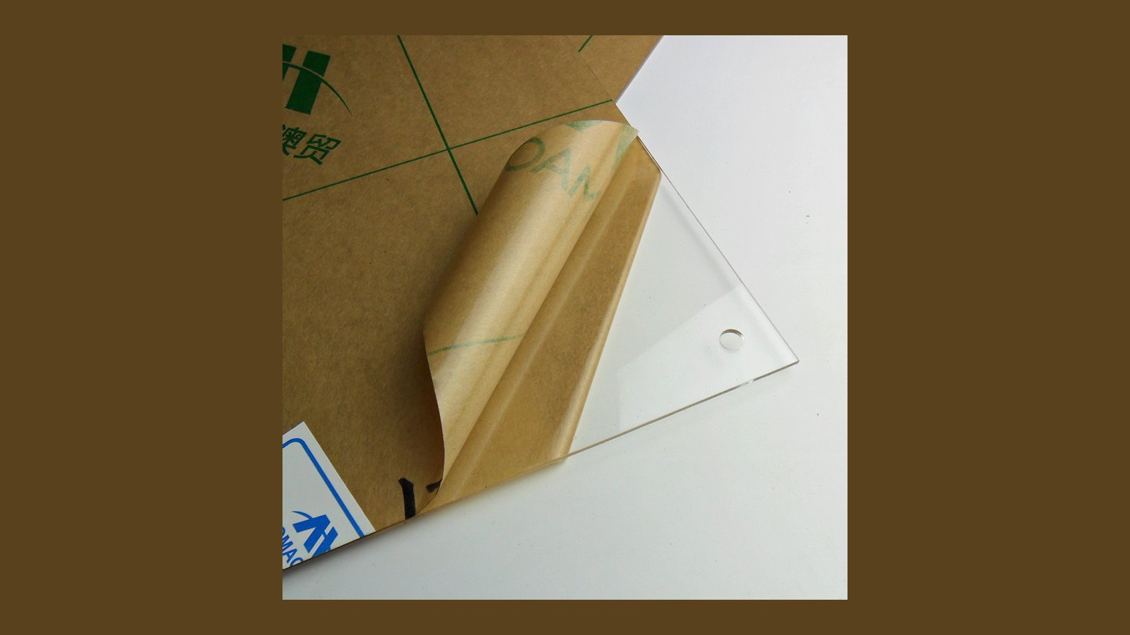
Protective acrylic shield and mounting hardware for your RggBer.

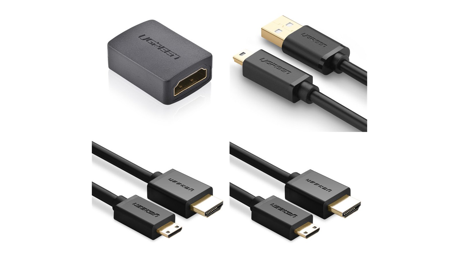
Connect your RggBer to your rig or another RggBer with this kit containing a high quality mini-USB cable, two HDMI cables, and an HDMI adapter. 1 x HDMI type A adaptor, female to female. 1 x mini USB to USB type A cable, 0.5 m. 2 x HDMI type C to type A cable, 1 m.

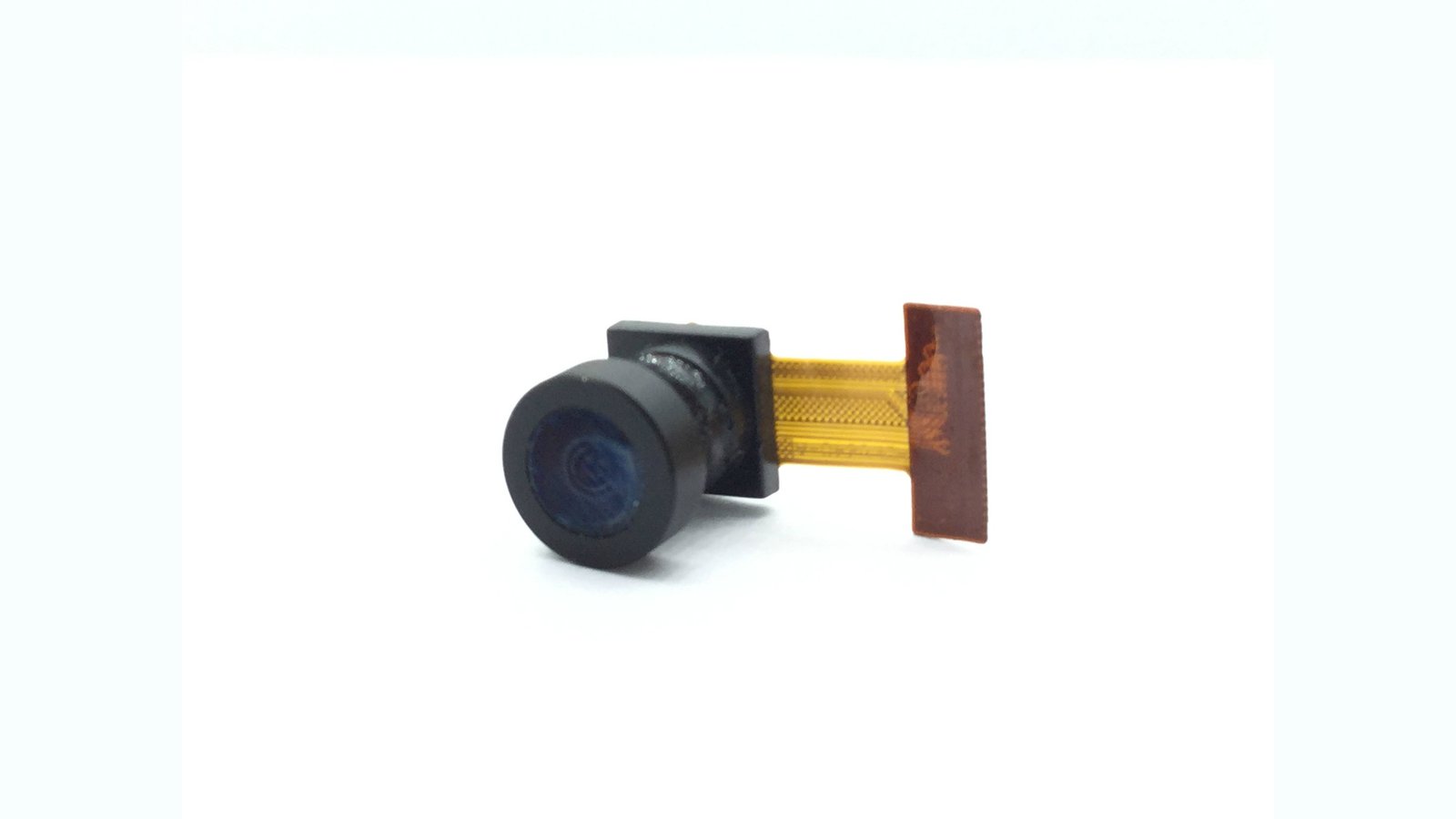
120-degree view angle, fixed-focus CIS module using an OV5640 sensor chip.