Project update 2 of 5
Flash Drive Design & Schematic
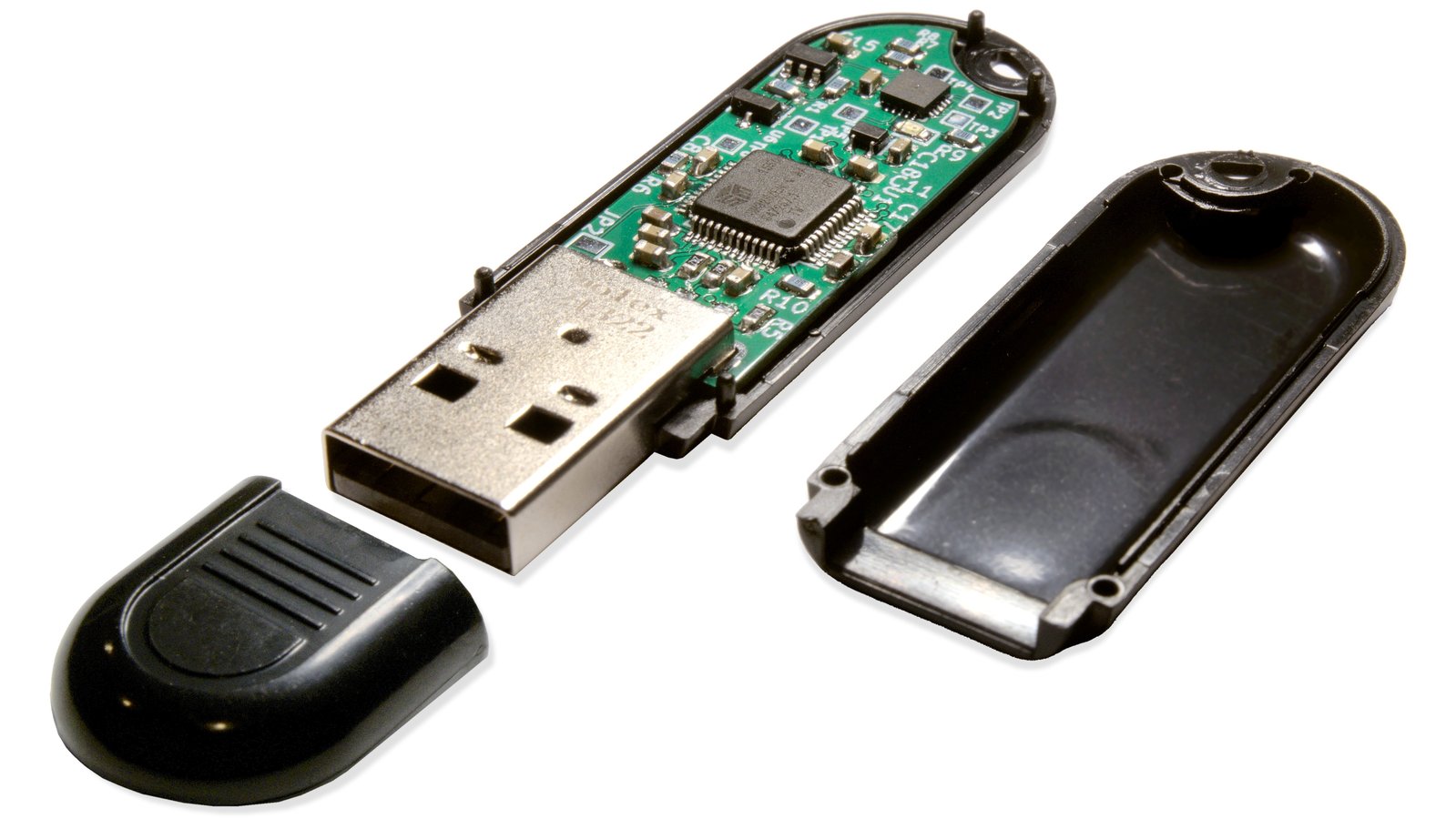
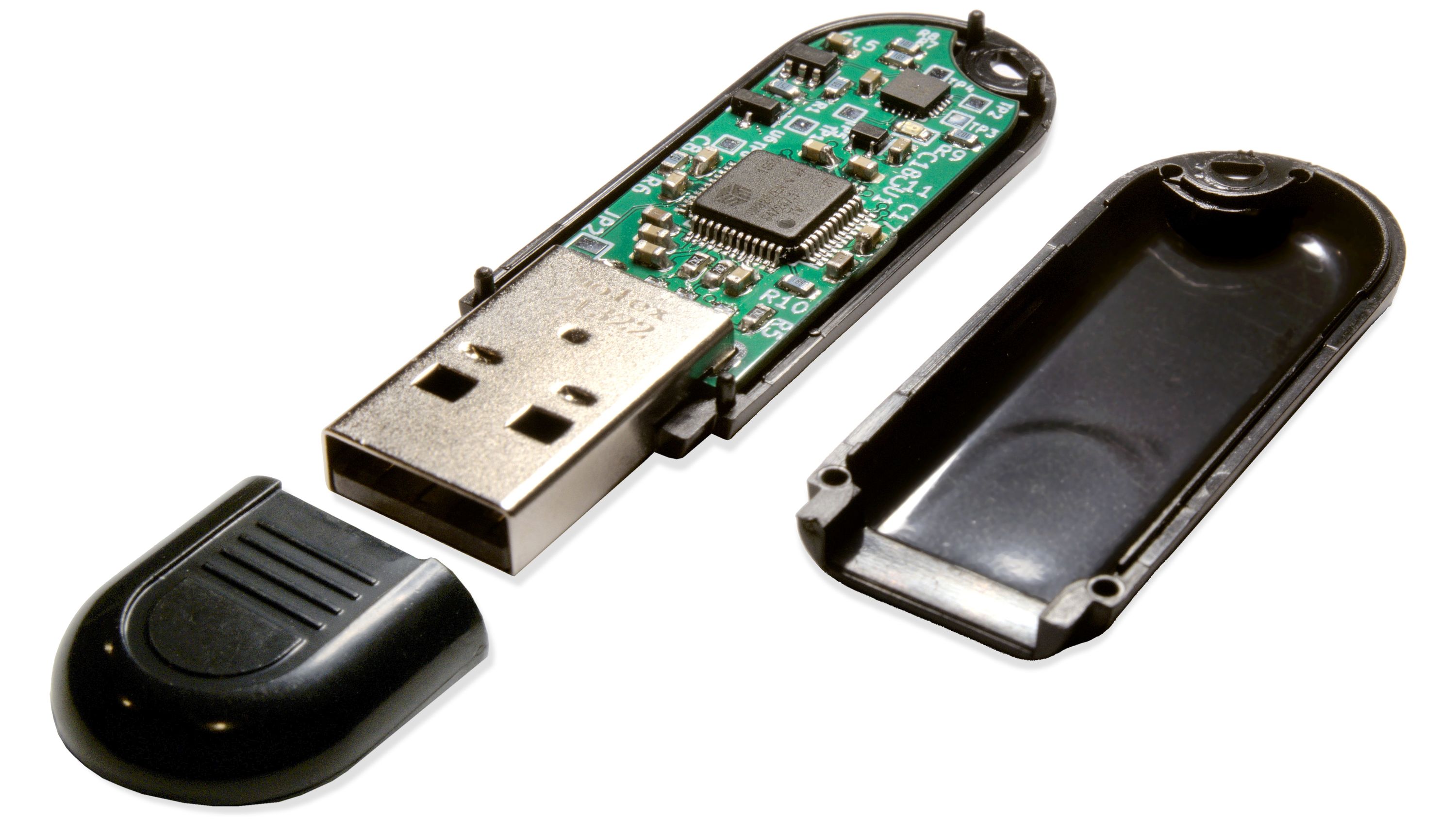
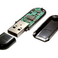
by Ryan WalkerOvrdrive USB is an open-hardware USB flash drive with an inconspicuous enclosure and a hidden security feature tucked away inside. If you plug in the device normally, it will appear blank, but if you quickly plug it in three times in a row, you can read and write data. Ovrdrive was built for journalists working in hostile environments, security researchers, and anyone interested in open hardware.
In this update, I’ll go over the schematic and speak to the design of a flash drive.
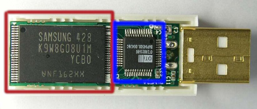
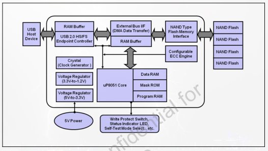
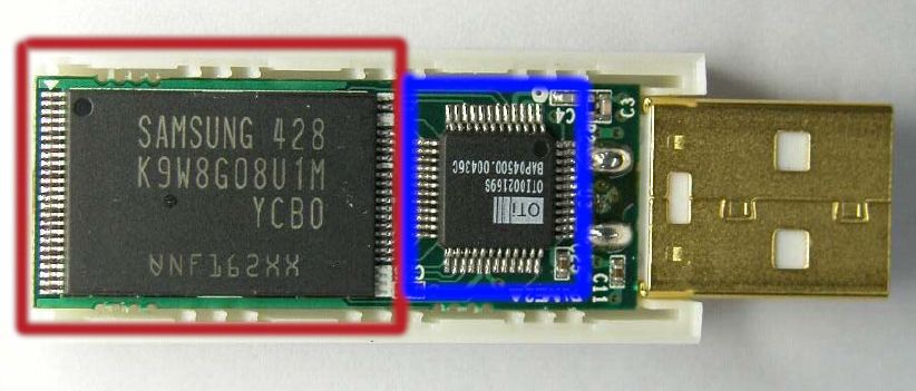
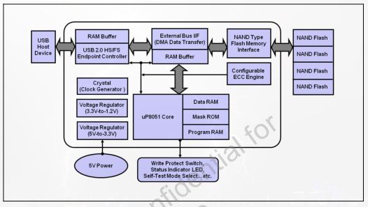
Flash drives are relatively simple, electrically speaking. The typical drive comprises a USB controller (blue) connected to a NAND flash chip (red). The flash chip holds all the data, while the controller contains a USB front end and logic to interface with the flash chip. In addition to the USB controller, I added a small microcontroller to inhibit the flash chip if required.
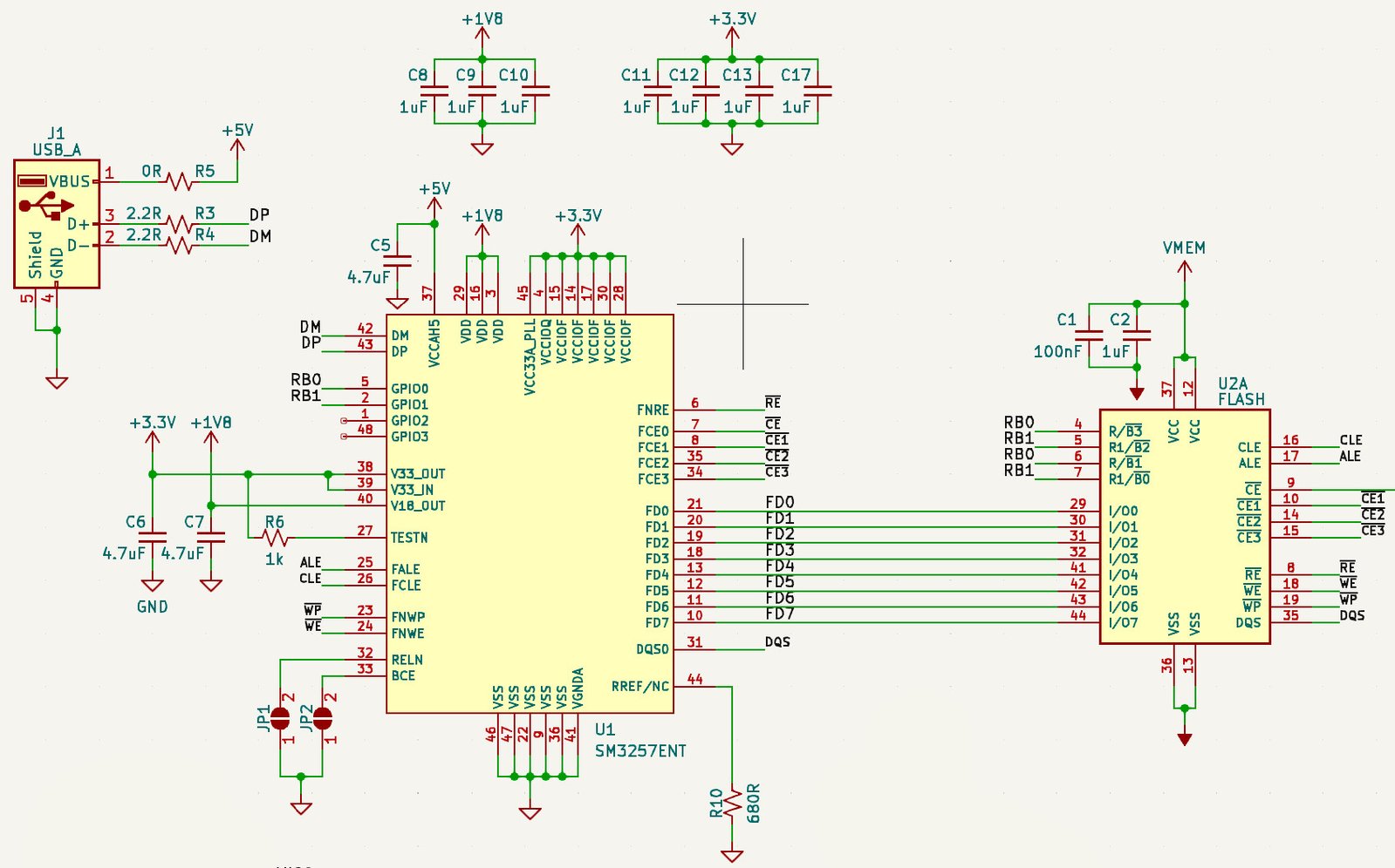
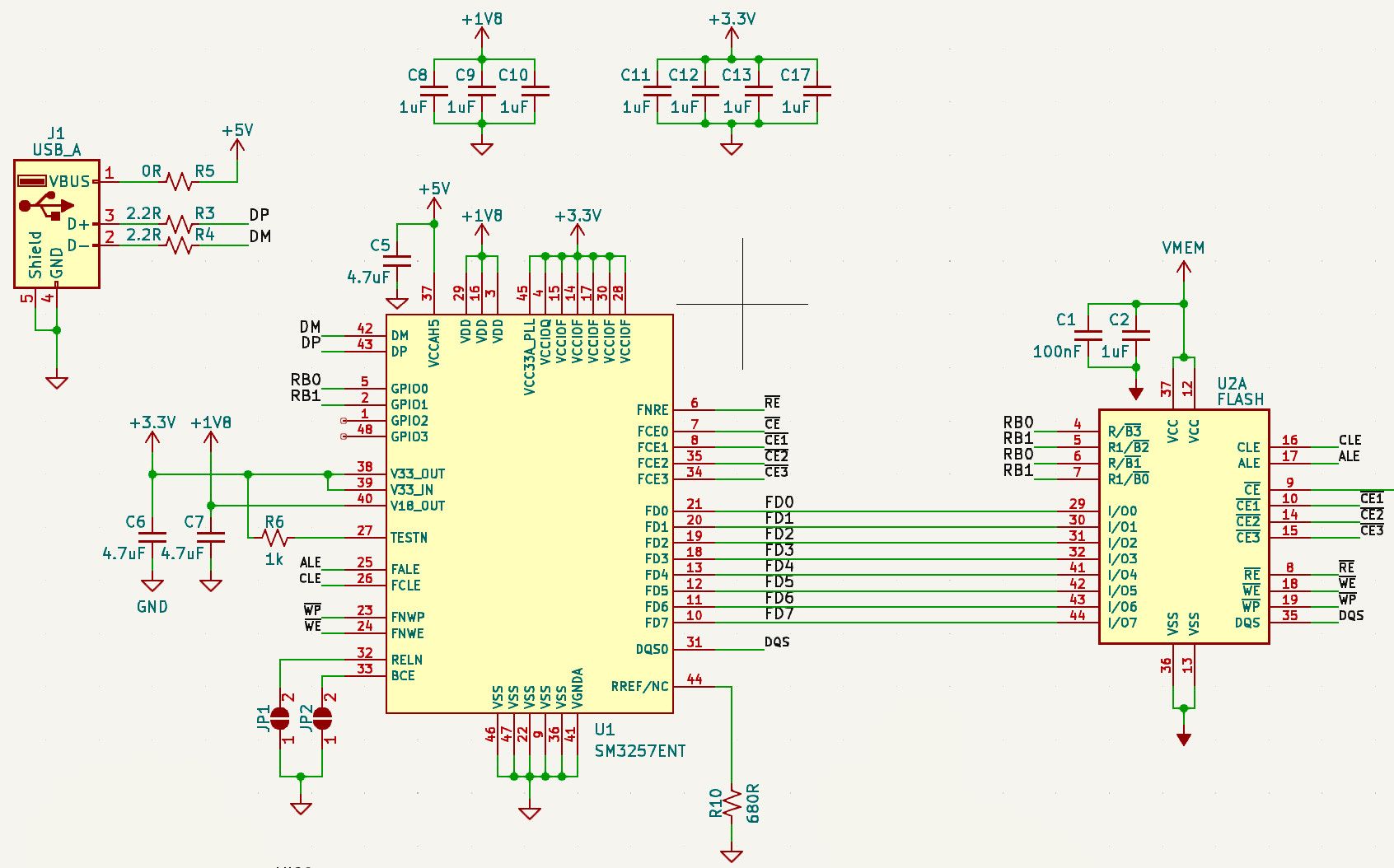
When selecting the flash drive controller, I searched the internet for flash drive teardowns, searched the text on the chips, and found a gold mine: a flash drive database listing part numbers for several USB controller ICs. I then checked to see if I could get a datasheet and a vendor — I settled on the SM3257EN.
The wiring between the USB port, flash controller, and NAND flash is straightforward. It uses an 8-bit data bus with some handshaking lines for control.
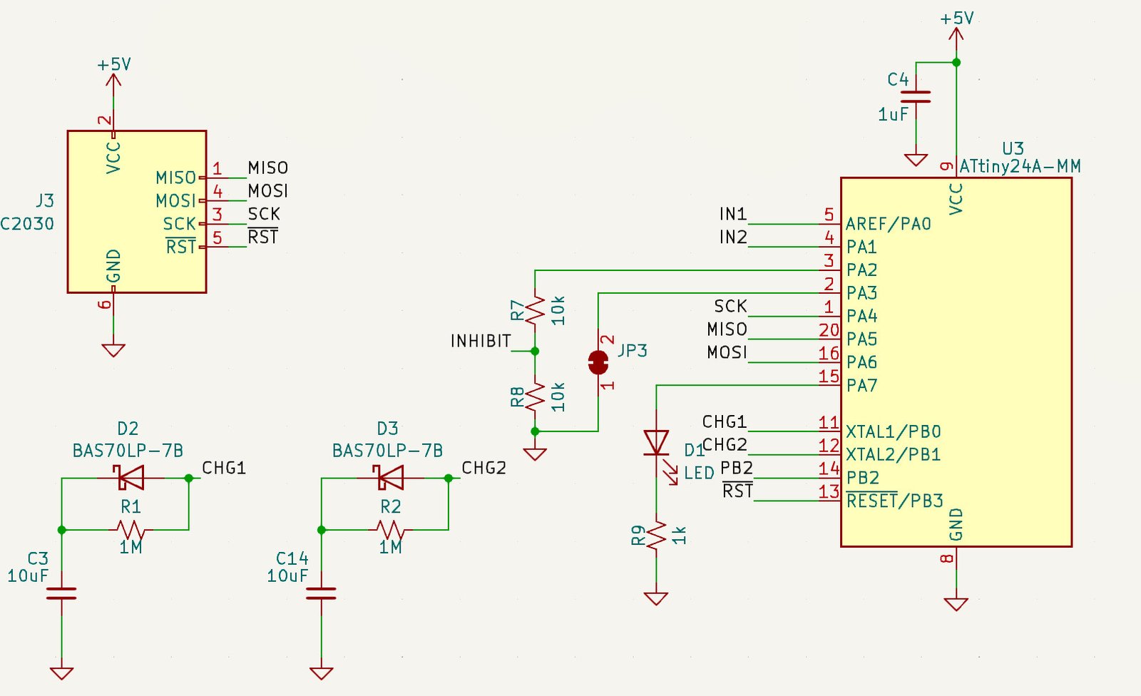
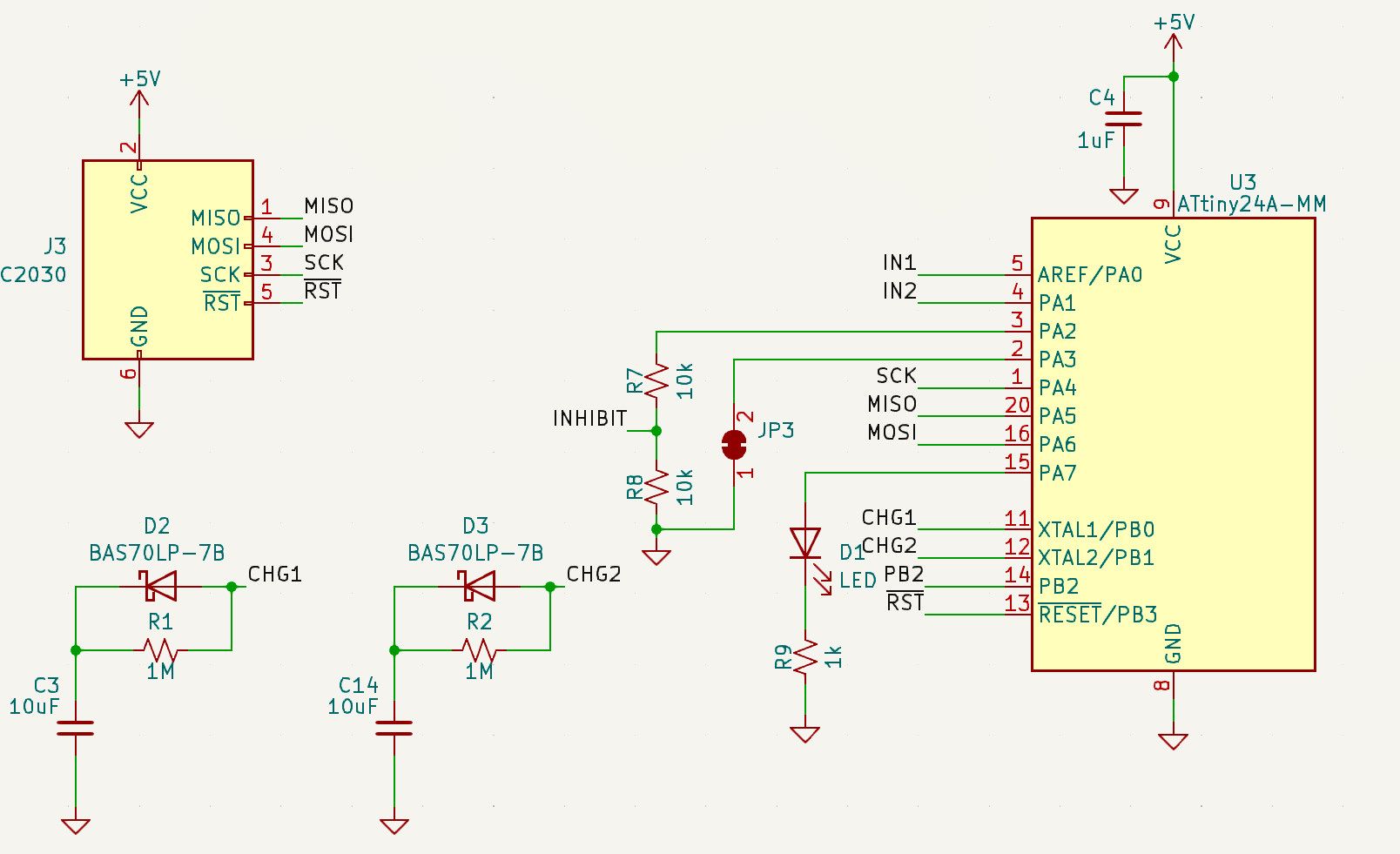
The circuit enabling the rapid plug-in functionality is also pretty straightforward; two identical circuits are connected to the microcontroller.
The above circuit works as such: when the CHG1 node goes high, it will charge C3 fast through D2. That pin will stay high for awhile regardless of the power applied to the device. C3 will slowly discharge through R1 and its body resistance.
So, C3 and C14 will stay high through a power cycling of the device or a rapid "plug/unplug/plug event."
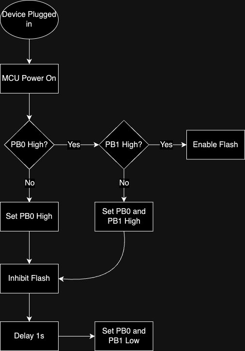
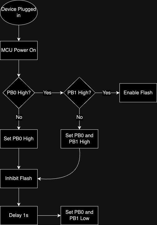
Above is a flow chart to illustrate what the code does. I will go into more detail about this when I discuss the firmware later. The final one second delay at the end is to prevent the issue of the user plugging in the drive, trying to get it to work, and then cycling the drive in and out. It ensures the plugging events have to be rapid.
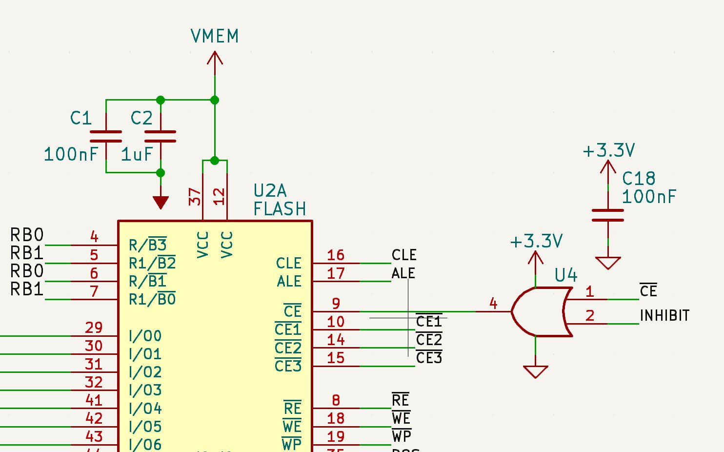
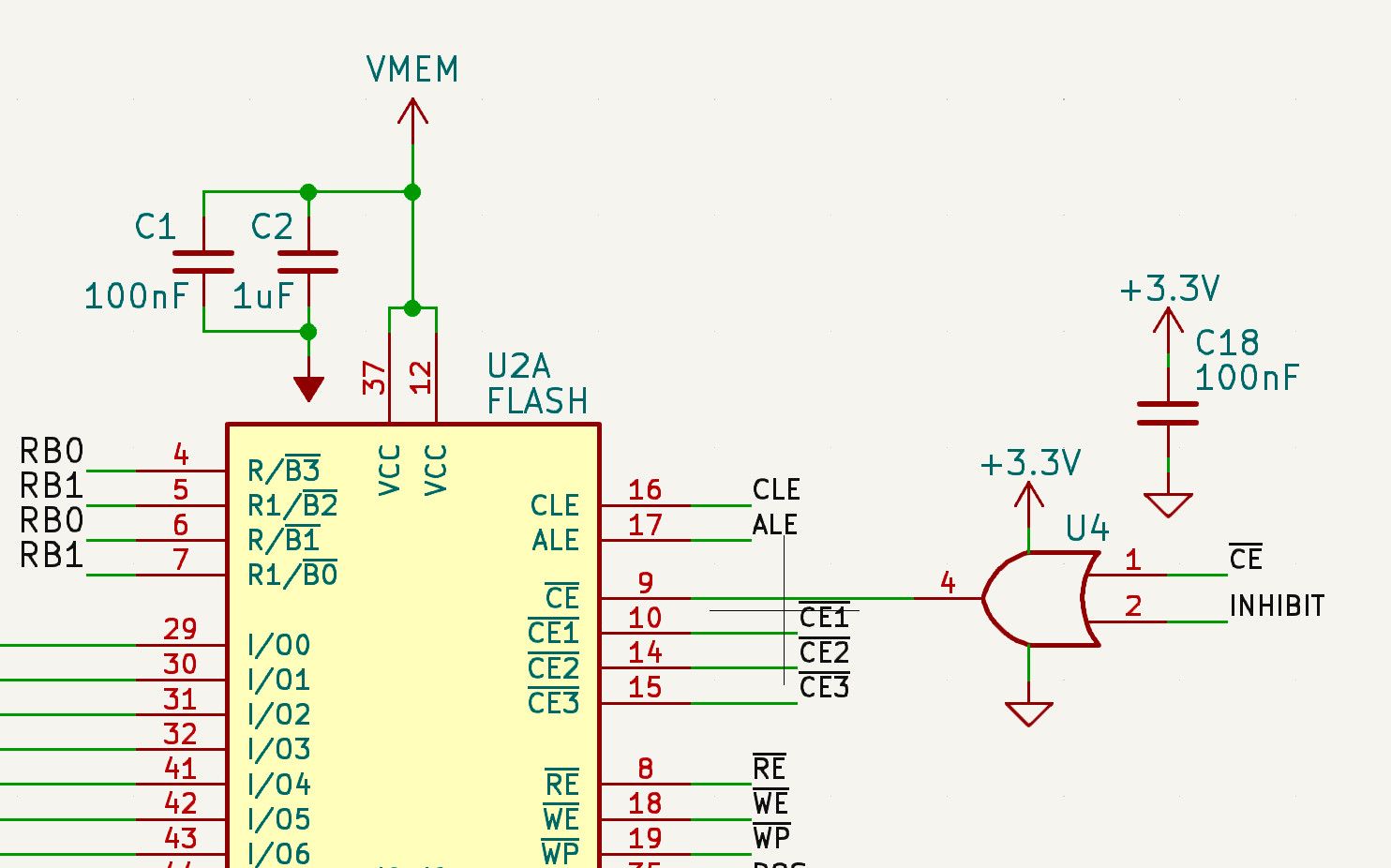
As for the inhibit circuitry itself, the "chip enable not" from the flash controller is "ORed" with a pin from the MCU. If the MCU sets this pin high, the flash controller will never be able to enable the flash drive, inhibiting the flash.
Those of you who have been following the project for a while know there were a lot of changes; there was a time when the user would have to lick their fingers to enable the drive. While hilarious, I pivoted away from that.
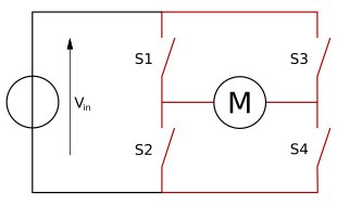
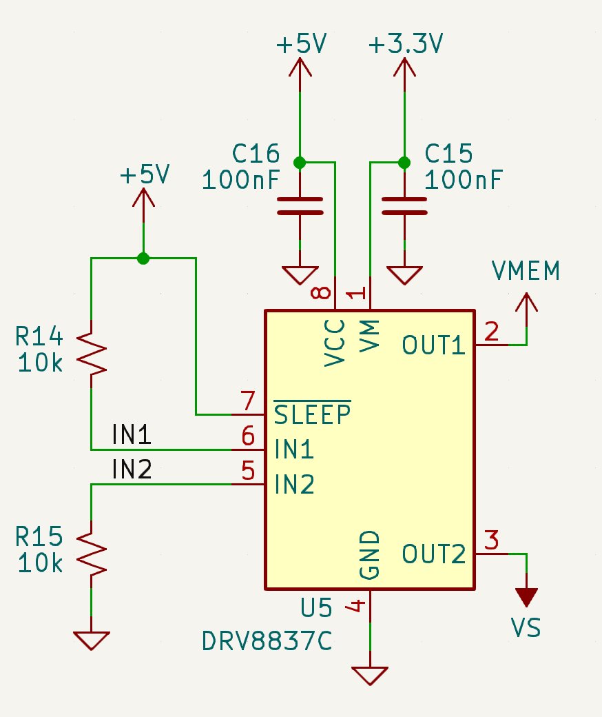
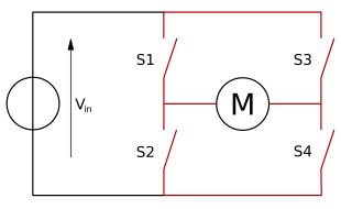
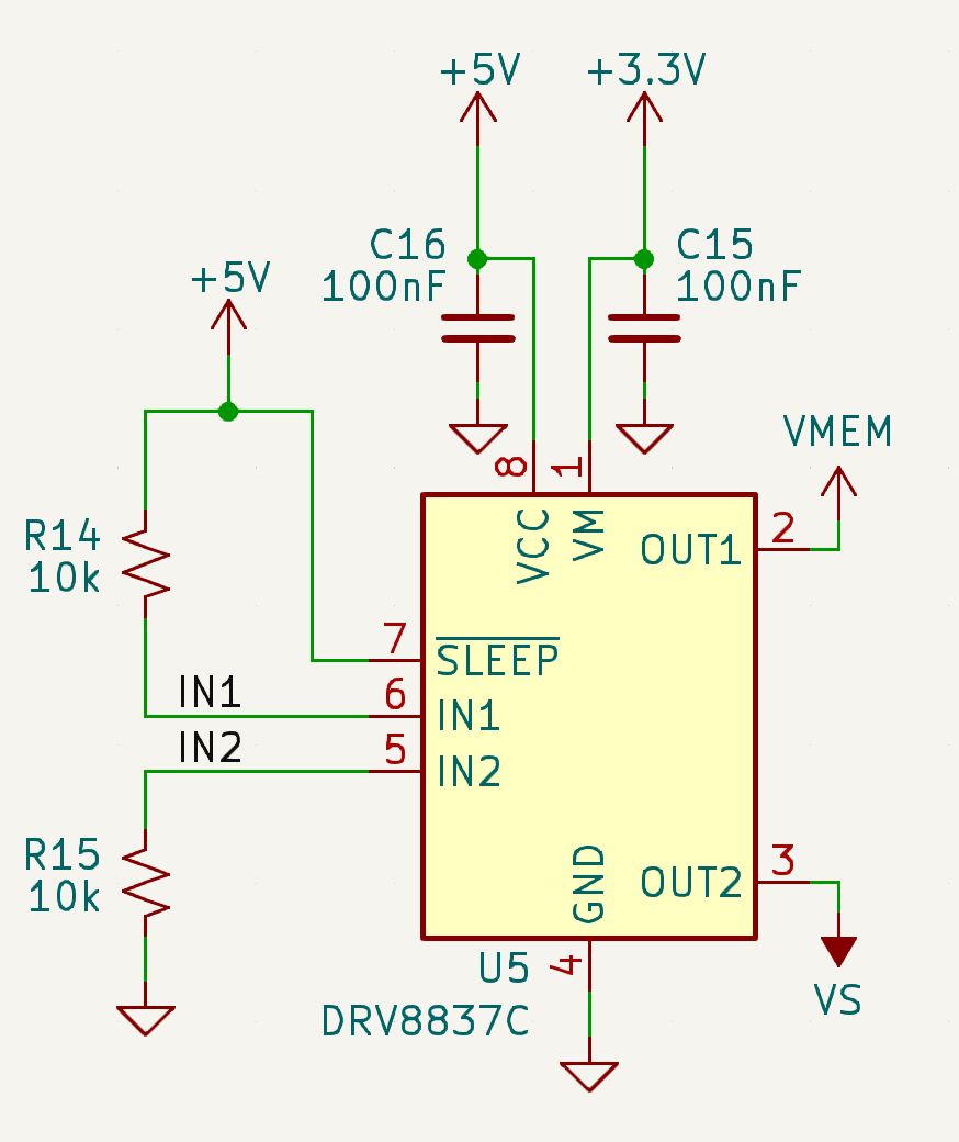
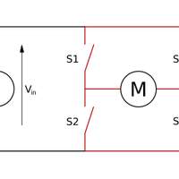
Another large change was the various destruction methods I implemented in the drive; I finally settled on powering the flash chip from an H-bridge. An H-bridge is a device traditionally used to power motors.
If S1 and S4 are on, the motor will rotate in one direction and if S3 and S2 are on, the direction will reverse. We use the same device to reverse the power to the flash chip, heating it and, in some cases, destroying it.
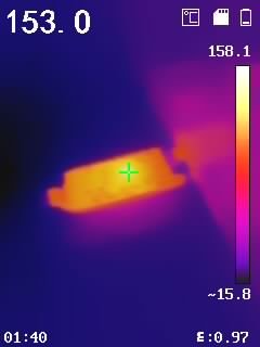
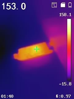
I used TI’s DRV8837C chip; you can read its datasheet for more information. From my tests, reversing the flash chip’s power will get it hot, but not hot enough for reliable destruction.
Thanks for tuning in. As you know, the project is completely open source so you can find the schematic here.
- Walker
