Project update 8 of 11
AdaFruit QT Py + BioAmp EXG Pill
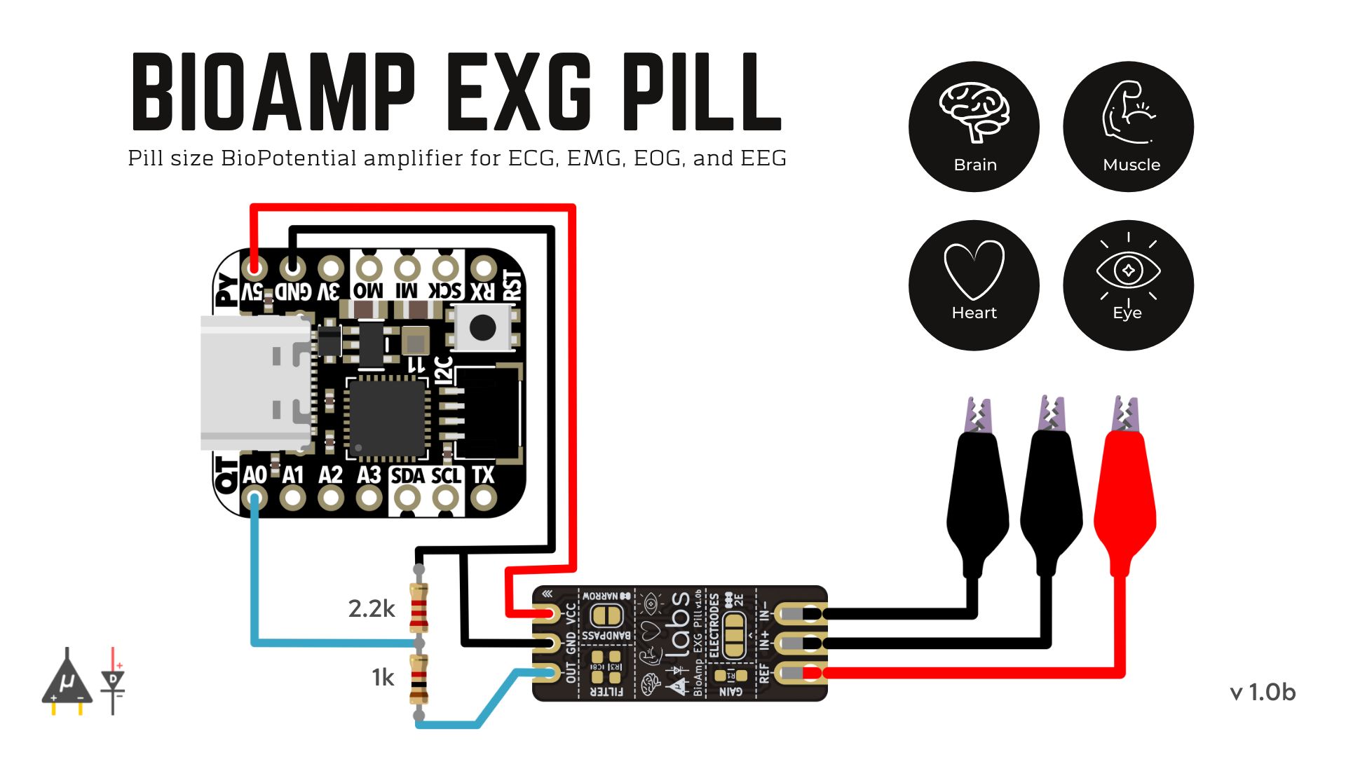
by Deepak KhatriBuilt around Microchip’s SAMD21, Adafruit’s QT Py (Cutie Pie) is indeed a cute little board. Its 12-bit ADC input is pretty good, and it can easily be coupled with BioAmp EXG Pill to record ECG, EMG, EOG, and EEG. To make this work, you will need to create a voltage divider using 2.2 k and 1 k resistors, as shown in the connection diagram below, and flash Fixed Sampling on to your QT Py.
Using that exact setup and our sample Arduino sketches, you can easily do Electromyography, Electrocardiography, Electrooculography, and Electroencephalography using your QT Py. We will share a connection diagram for each of these setups below, but first have a look at this video, which shows ECG, EMG, EOG, and EEG recorded using the QT Py + BioAmp EXG Pill setup thanks to generous help from John Vivek.
Electromyograph
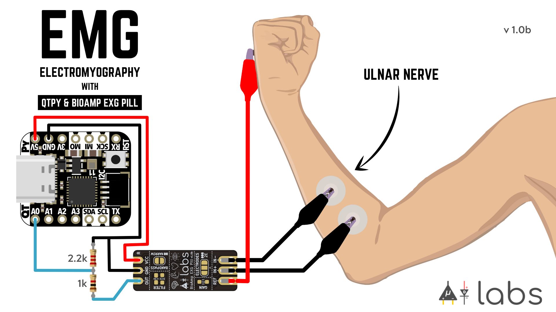
To make an Electromyograph for recording EMG signals using Adafruit’s QT Py and BioAmp EXG Pill, configure the circuit as shown in the image below, flash the EMG-filter Arduino sketch onto your QT Py, and open up the serial plotter of your Arduino IDE.
Checkout the Electromyography (EMG) Walkthrough project update for information about EMG filtering, envelop detection, servo control, and LED-bar control, as well as an exciting project demo that relies on EMG data recorded with BioAmp EXG Pill.
Electrocardiograph
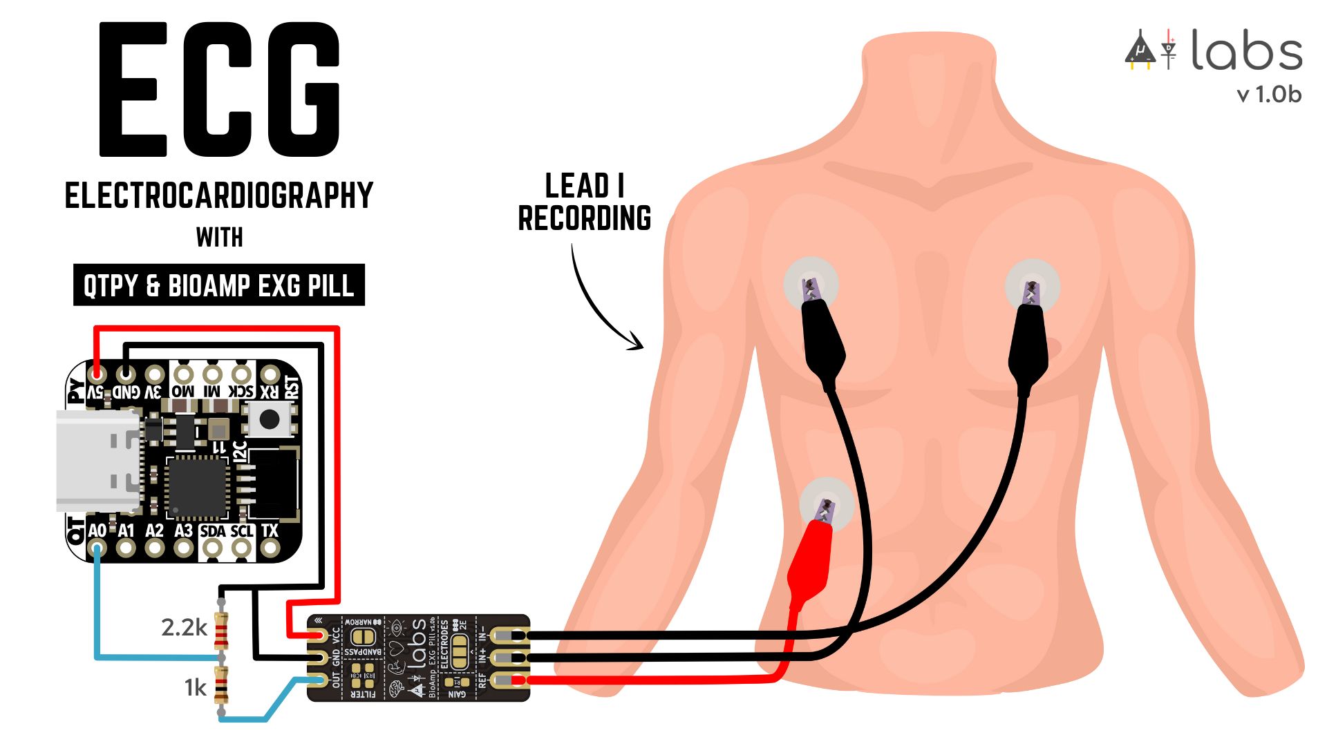
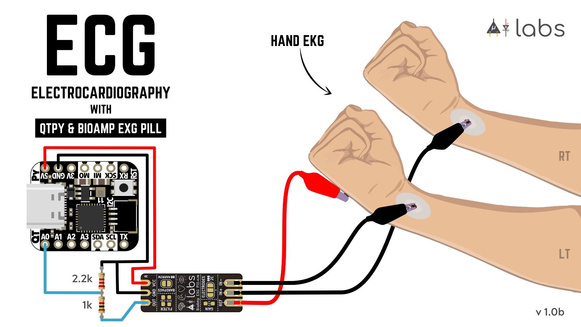
To make an Electrocardiograph for recording ECG signals using Adafruit QT Py and BioAmp EXG Pill, configure the circuit as shown in the images below, flash the ECG-filter Arduino sketch onto your QT Py, and open up the serial plotter of your Arduino IDE.
Checkout the Supportive Technology project update for information about ECG filtering and heart-beat detection, and more on ECG recording, with BioAmp EXG Pill.
Electrooculograph
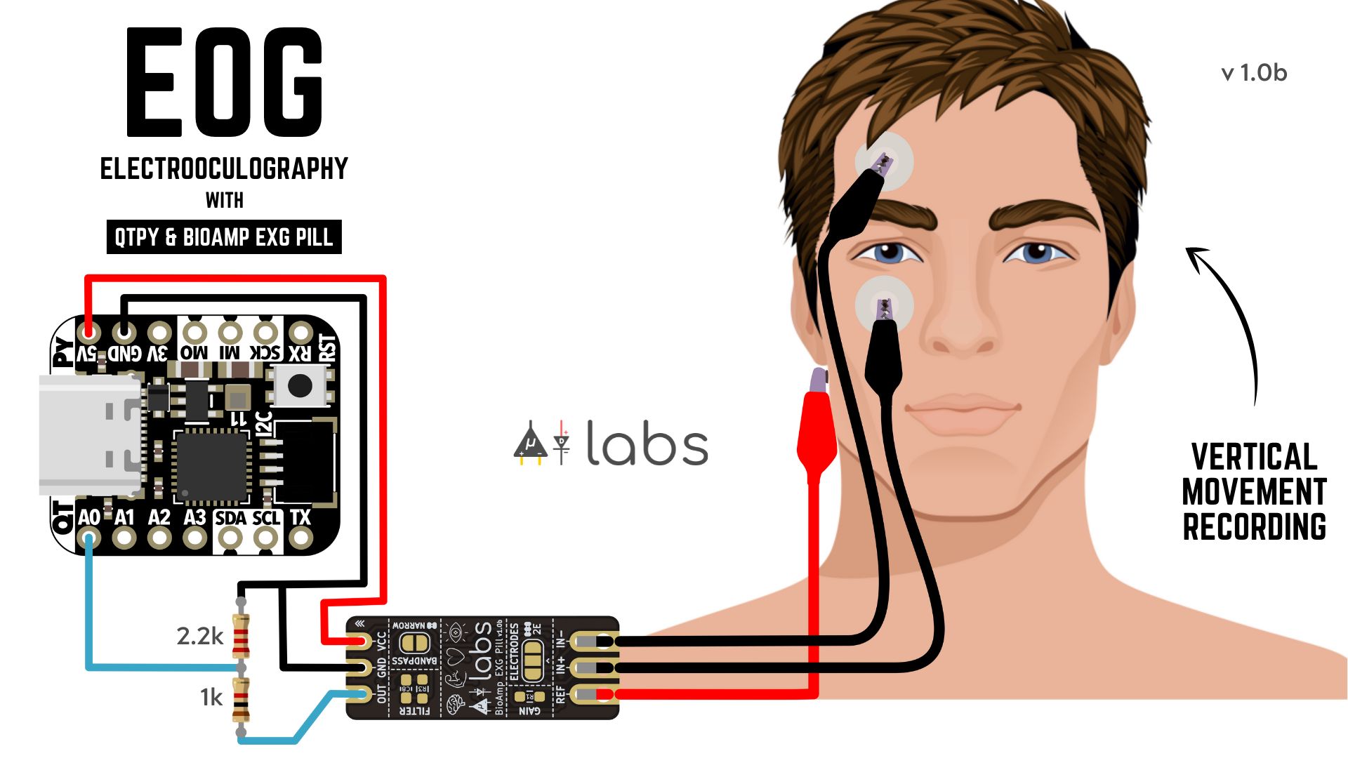
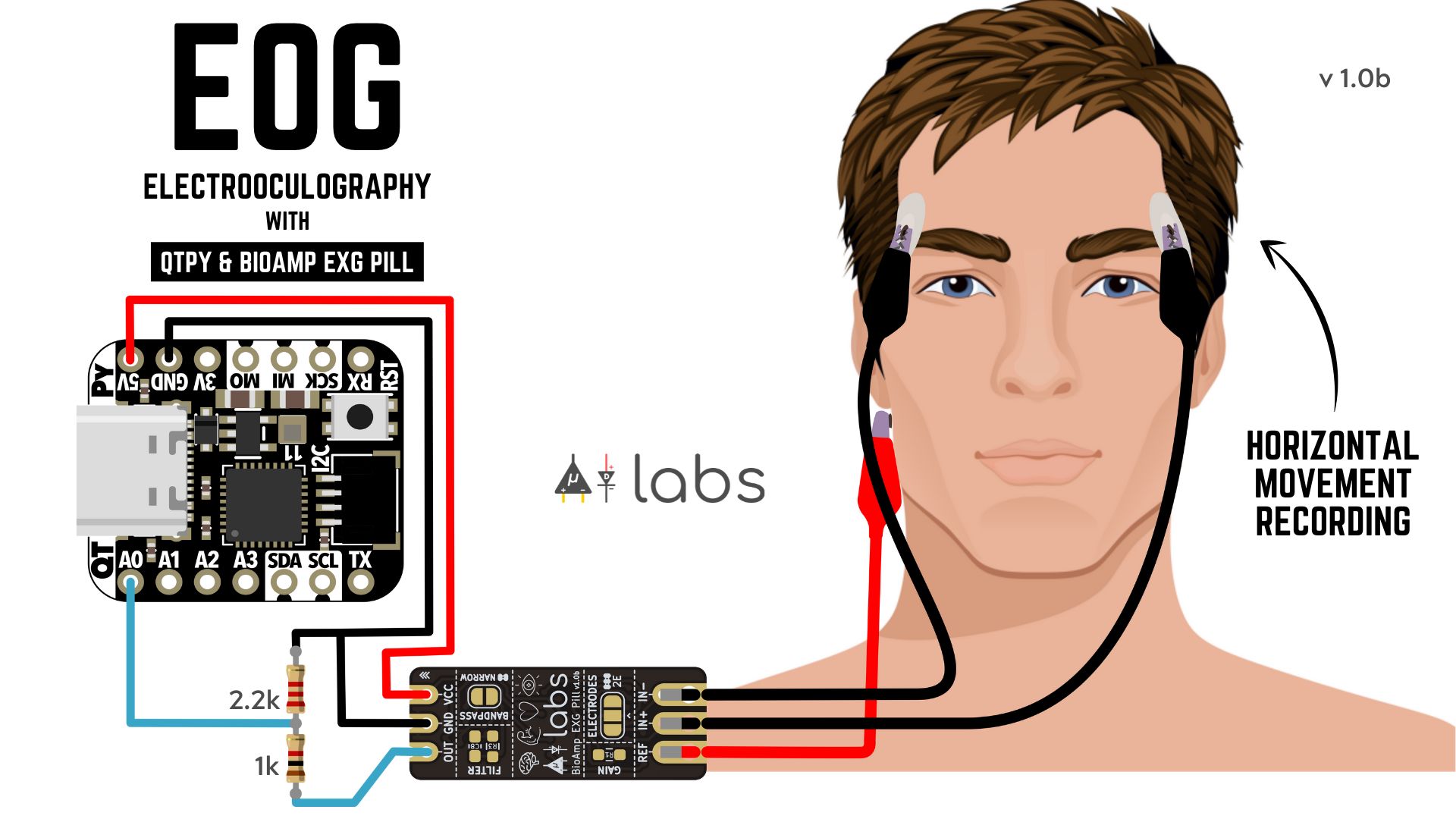
To make an Electrooculograph for recording EOG signals using Adafruit QT Py and BioAmp EXG Pill, configure the circuit as shown in the images below, flash the EOG-filter Arduino sketch onto your QT Py, and open up the serial plotter of your Arduino IDE.
Checkout the Electrooculography (EOG) Walkthrough project update for information about EOG filtering and eye-blink detection, and more on EOG recording, using BioAmp EXG Pill.
Electroencephalograph
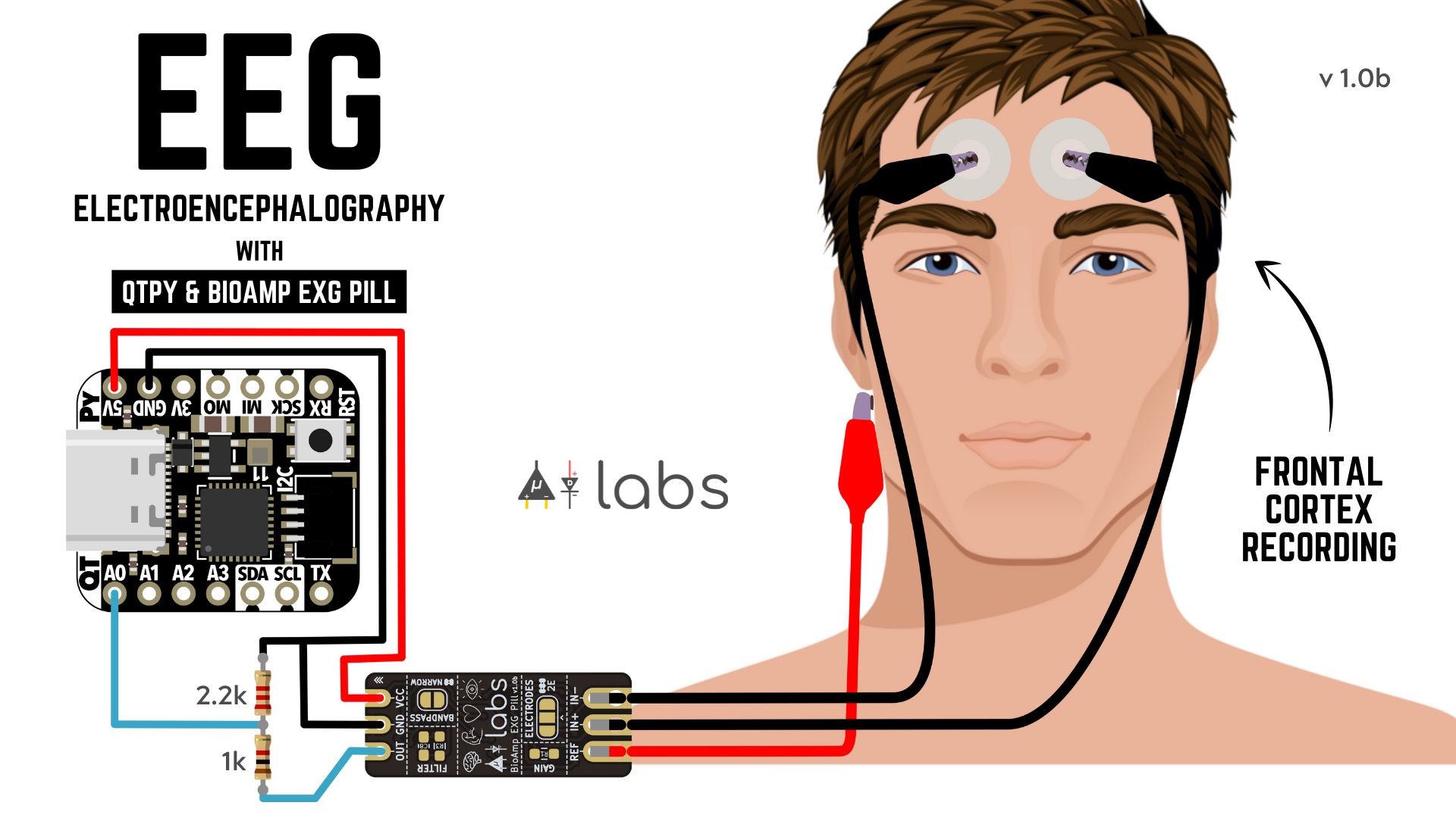
To make an Electroencephalograph for recording EEG signals using Adafruit QT Py and BioAmp EXG Pill, configure the circuit as shown in the image below, flash the EEG-filter Arduino sketch onto your QT Py, and open up the serial plotter of your Arduino IDE.
Checkout the Electroencephalography (EEG) Walkthrough project update for information about EEG filtering, and more on EEG recording, with BioAmp EXG Pill.
What’s next?
In our next project update, we will enable our EXG setup to connect to Bluetooth and Wi-Fi using its ESP32. You can build some awesome projects with this setup, for example this EOG-based BLE "remote shutter release", which was created by Padmalaya Rawal of PR Robotics. Or you could create a new T-Rex game controller that interprets an eye blink as the press of a space bar on a Bluetooth keyboard. Possibilities are endless, and we are very excited to watch what you will be making with your own BioAmp EXG Pill!
BioAmp EXG Pill review video
NNNI recently posted an awesome BioAmp EXG Pill review video on YouTube. It’s pretty cool, but please keep in mind that it’s not, by any means, a complete review. It only shows some of the biopotential signal recording that BioAmp EXG Pill can handle. Also, some assumptions were made while testing the device’s real capabilities. To help clear up any doubts, I have shared some pointers below that might help you make sense of what’s going on in the video.
First of all, I would like to thank NNNI for making such a detailed video! I enjoyed it very much! Below are a few related suggestions that will help you make the right decisions while using BioAmp EXG Pill in a project:
- The gel electrode patch has a non-sticky tab that is supposed to go in the opposite direction of hair growth. During the removal of the gel electrode, you pull the patch in the same direction of your hair growth with the help of that non-sticky part of the gel electrode.
- The refAmp 1k resistor is used for current limiting and, with a properly grounded setup, the noise doesn't appear at all. Putting a 0-ohm resistor makes no difference. BTW, we used 100k resistors for all three input pins in v0.7 which are dropped in the v1.0x because they made the EXG Pill noisy.
- Band limiting is very useful for EOG and EEG recording, which are not shown in this review video. Also, the signal sometimes clips while recording ECG with electrodes very close to the heart. Creating a solder jumper for a band-pass filter helps with that.
- The gain option, which is not shown in this review, is very useful for EEG and EMG recording. If you record EMG and EEG, you will find that the signal coming out of BioAmp EXG Pill is very low in amplitude in comparison to EOG and ECG signals. Increasing the gain is something that can help.
- The two-wire mode is specifically included for projects like ECG-acquisition patches, heart-patch projects for HRV, etc. It's only supposed to be used with a battery-operated setup and is quite prone to high interference noise due to a lack of proper reference on the body.
Again, removal of the DRL resistor is something we know can help you obtain a stronger signal. We especially chose to go with 1k instead of 0-ohm to make the device a little bit safer. It’s true that not everybody will have a properly grounded setup, and some BioAmp EXG Pill users will likely want a cleaner signal instead of this current limiting. After seeking out additional feedback from our beta testers, we might change the 1k resistor to 0-ohm for the final PCBs.


