Project update 6 of 8
Preparing for Production
by Signaloid TeamDear Subscribers,
We have been further developing and fine-tuning our production process for the Signaloid C0-microSD. In this update, we provide an overview of our setup for loading the initial bootloader firmware, automated testing of each device, and packaging the final boards before shipping them to backers.
Manufacturing Plan
We will outsource the PCB fabrication and assembly to PCBWay. When we started developing the C0-microSD in 2021, we manufactured the first design iteration using a number of different printed circuit board manufacturers in the UK, Germany, and China, and we ended up settling on using PCBway for later design iterations. (In a later update, we will share a detailed timeline and pictures of these different revisions.) PCBway will deliver the assembled boards to us in panels of five. We will separate the individual boards from the panels, perform visual inspection of the individual cards, load the bootloader firmware onto each C0-microSD to enable it to be subsequently programmed through the microSD interface, and then conduct operational tests using a testing setup which we further detail below.
Separating the Panelized, Assembled Circuit Boards
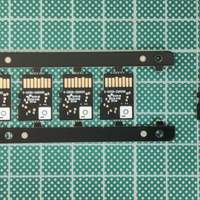
PCBWay will deliver the assembled boards to us in panelized form, using the "mouse bites" technique for panelizing very thin PCBs. Once we separate the boards and clean up the residual mouse bites, we visually inspect the boards and load the bootloader FPGA bitstream which will allow subsequent configuration of the FPGA using block I/O operations over the SD interface.
Flashing and Testing the Signaloid C0-MicroSD
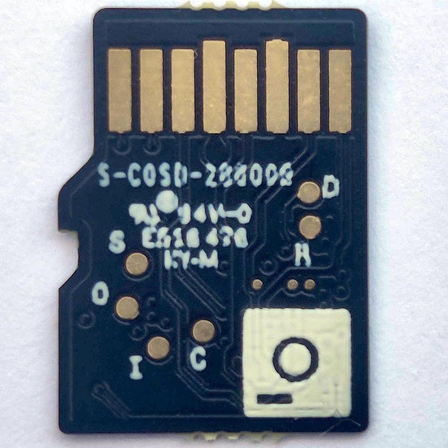
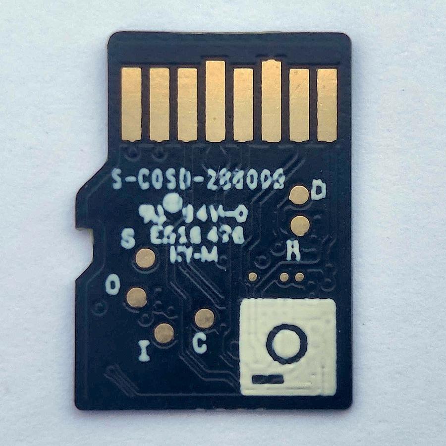
The Signaloid C0-microSD features an on-board, 128 Mbit (16 MB) SPI flash IC. It is used for storing FPGA bitstreams, user firmware, and data for the SoC mode. When we receive the boards from the factory, this flash IC is empty. To enable the Signaloid C0-microSD’s SD interface programming, we must first load our custom bootloader FPGA logic that implements the SD block I/O interface into the flash IC using the flash IC’s SPI interface (which we have made accessible via test pads on the bottom surface of the circuit board). These test pads are 0.4 mm in diameter, with a minimum distance (center to center) from each other of 1.0 mm. To interface between a host PC controlling the flash programming and the flash IC, we use a Tigard.
The Programming and Testing Jig
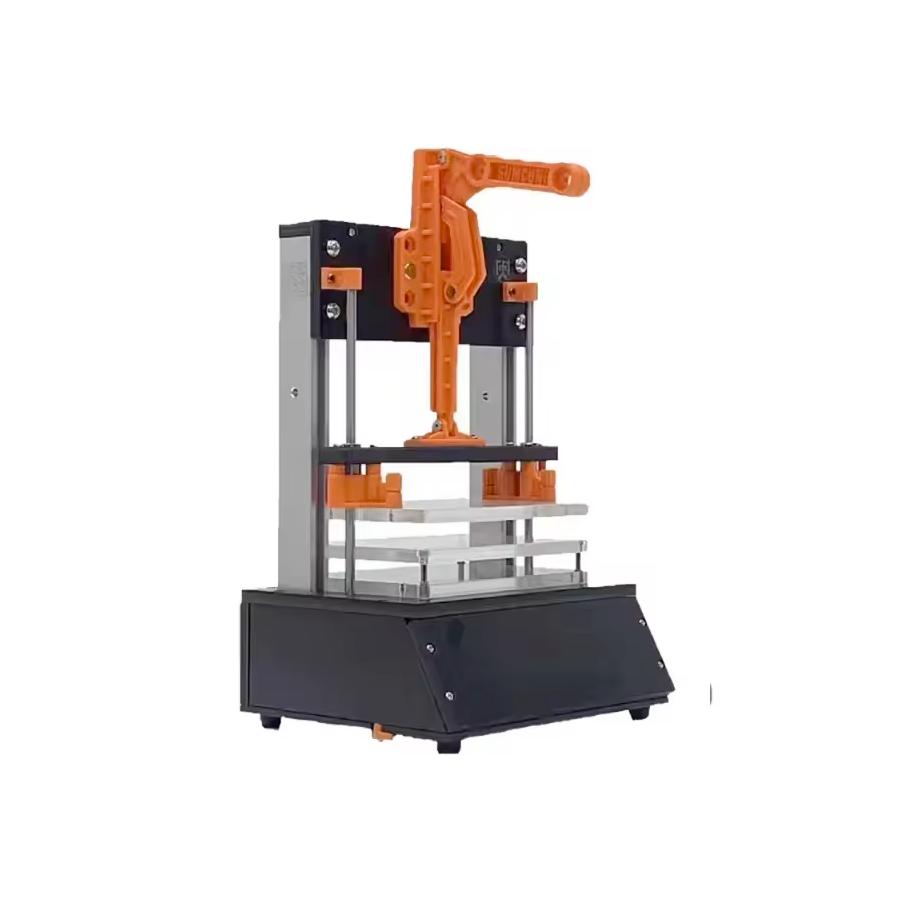
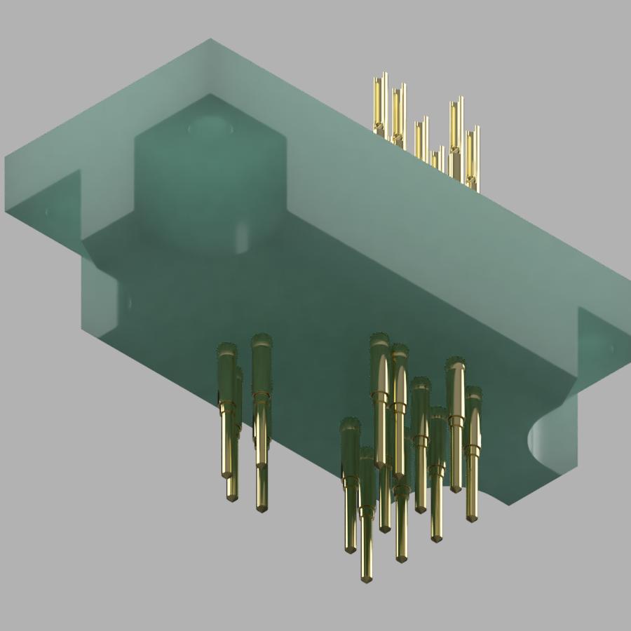
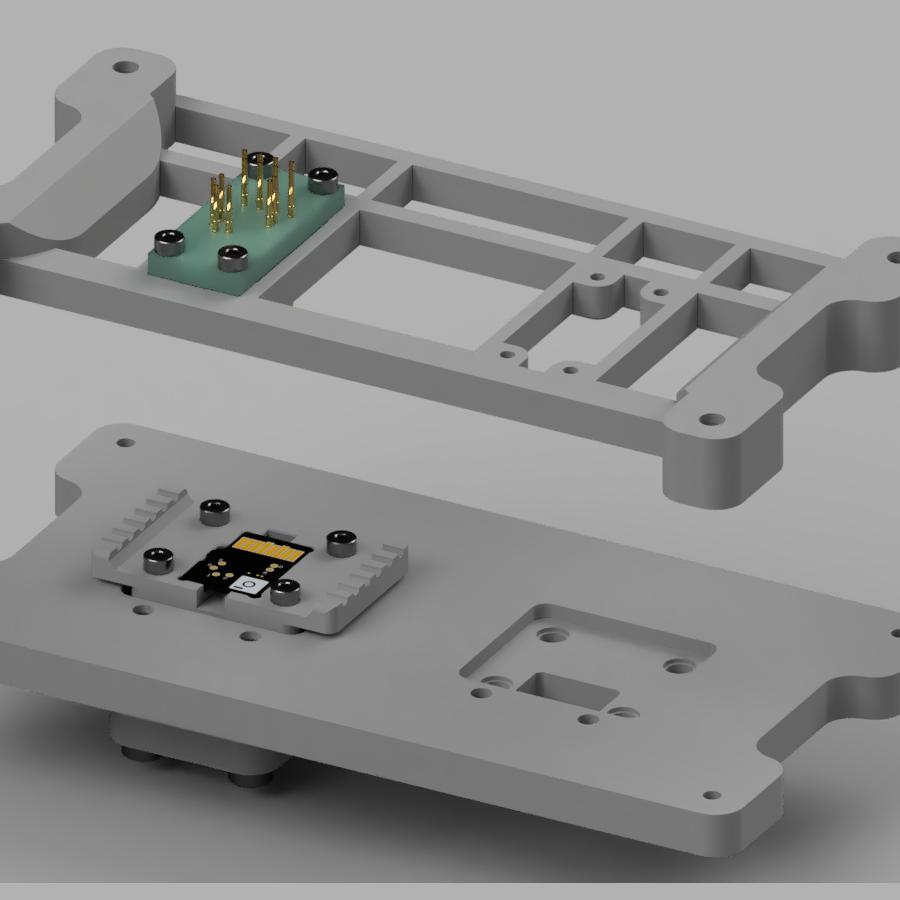
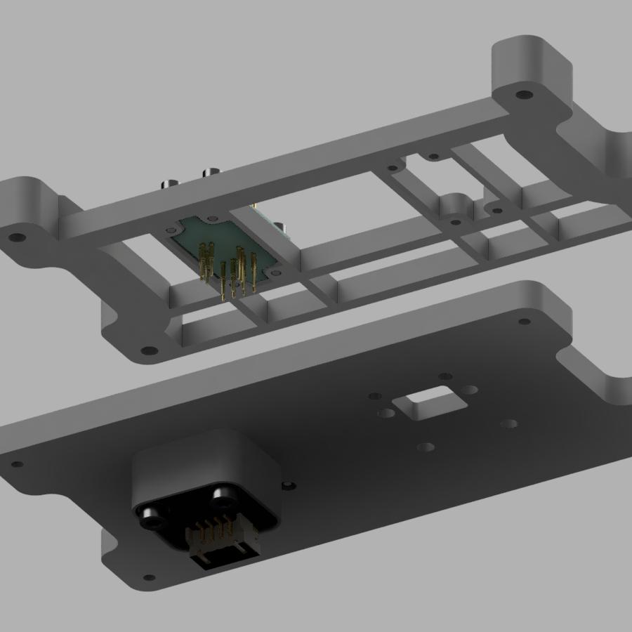
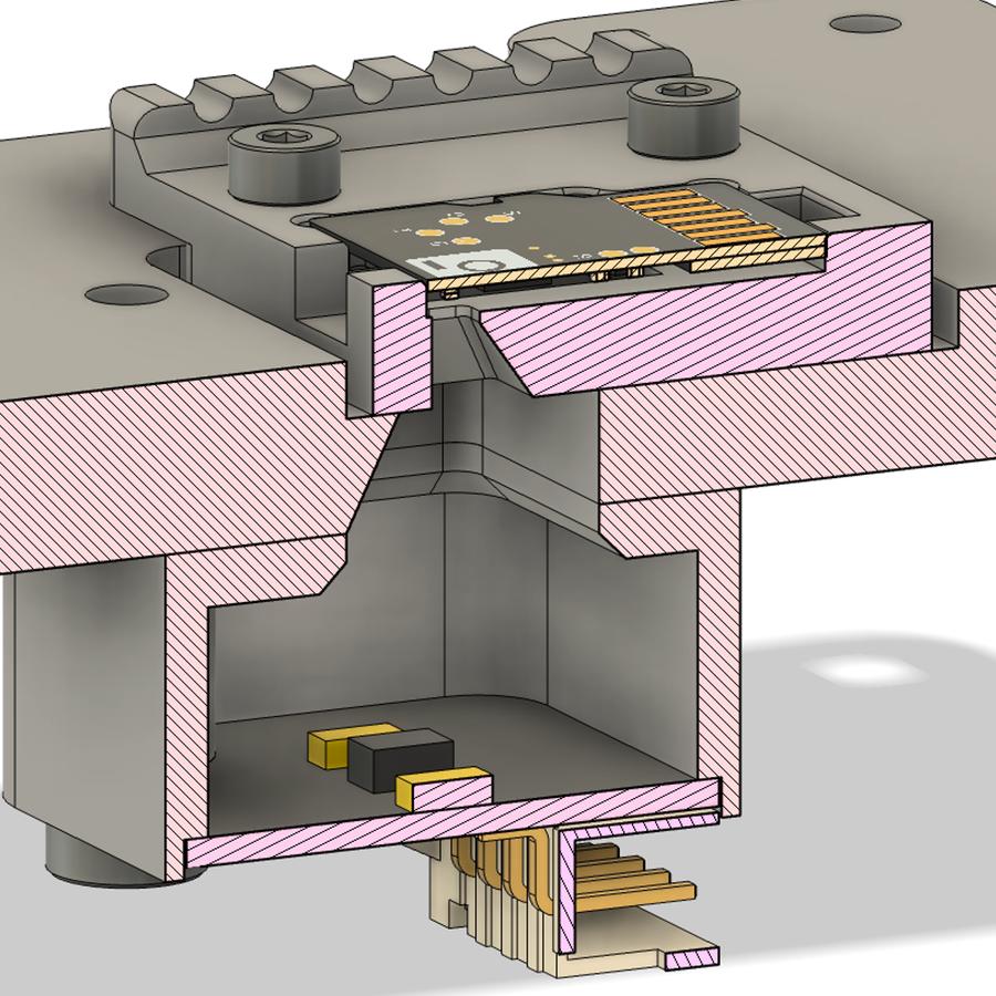
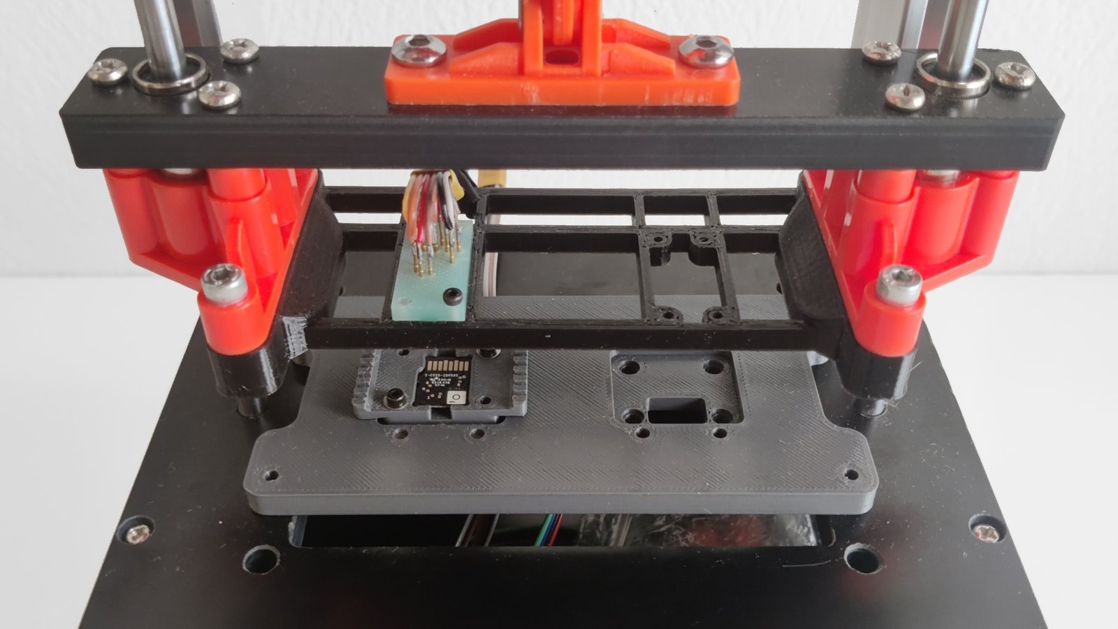
To interface reliably with the programming pads, we developed a programming “jig” based on a universal PCB testing frame. The component that interfaces with the Signaloid C0-microSD is the plunger: a piece of FR4 material milled to hold 14 spring-loaded pins, using a set of receptacles. The plunger is responsible for correctly aligning the programming pins in relation to each other, while keeping them electrically isolated. We chose the total count of 14 pins so we could also include connections to the SD interface, which we will need to test the SD block I/O behavior of programmed devices in situ after loading the bootloader FPGA logic over the test pads.
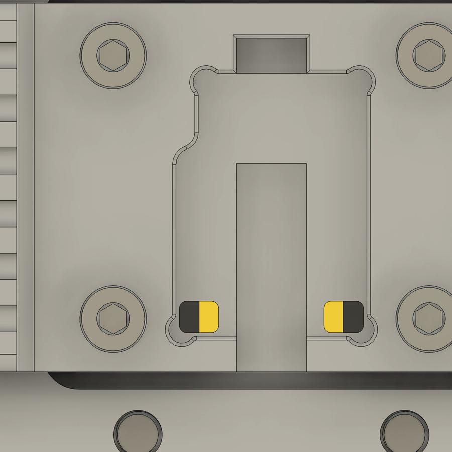
We use this jig both to program each C0-microSD and to test each C0-microSD card. To facilitate testing the functionality of the two LEDs at the lower edge of each C0-microSD(which indicate whether it is in bootloader mode or in Signaloid SoC mode), we included an I2C color sensor at the back of the bottom plate, which connects to the host computer that controls the testing process. We designed the holder and the bottom plate to block all ambient light and to only let the light emitted from the LEDs reach the sensor.
We intend to use this jig not only to program, but also to test the Signaloid C0-microSD cards. For that reason, we included an I2C color sensor at the back of the bottom plate, which can test the correct functionality of the two onboard LEDs of the device. The holder and the bottom plate are designed to block all ambient light and only let the light emitted from the LEDs reach the sensor.
The picture below shows the assembled jig set up to test only one Signaloid C0-microSD at a time. We have, however, designed the top and bottom plates to accept up to two plungers, to enable us to handle up to two boards at a time. In the picture below, the bottom plate is attached to the base of the universal PCB testing frame using four M3 screws and the top plate is attached to the moving part of the frame using four M4 screws.
Loading FPGA Bitstreams Onto the On-Board 128 Mbit (16 MB) SPI Flash IC
We use iceprog (which is a part of the open-source icestorm toolkit) to program the SPI flash IC which the iCE40 FPGA in the C0-microSD uses to load its bitstream at power-up. We have also developed a Python application which generates a serial number and UUID pair, and then programs these into the SPI flash IC’s one-time programmable (OTP) sector. These values are the serial number and UUID returned when using the -i option in the C0_microSD_toolkit Python application. In the following example, the serial number of the device is S-C0-00-1D002B:
sudo python3 C0_microSD_toolkit.py -t /dev/disk4 -i
Signaloid C0-microSD | Loaded configuration: Bootloader | Version: 1.0 | State IDLE
Device Serial Number: S-C0-00-1D002B
Device UUID: d0169385-236f-4795-8cd7-3cda4687c584

...
Done.
Testing the Signaloid C0-MicroSD
In addition to flashing the Signaloid C0-microSD, we have also developed a series of unit tests that ensure the proper functionality of the bootloader, the Signaloid SoC, and the on-board LEDs. We run these tests using the SD-Dev in standalone mode (i.e., with a Raspberry Pi CM4 attached), taking advantage of the capability we designed into the SD-Dev to programmatically power cycle the on-board SD devices to program the Signaloid C0-microSD and switch between operation modes. To connect the plunger to the SD-Dev, we use an SD sniffer board.
Additional Automation of Packaging and Labeling
We will package each Signaloid C0-microSD in an anti-static bag, with a label that includes its serial number and UUID. We have designed our flashing and testing script to automatically print, using a thermal transfer label printer, a unique sticker label to be affixed to each anti-static bag as the last step of the packaging process.
In the next update, we will share a detailed timeline and pictures of the different revisions of the Signaloid C0-microSD, from our first prototype in 2021 to the final production version we are now putting through CE, UK-CA, and FCC certification using a well-known certification laboratory.
Best regards,
The Signaloid team

