Project update 5 of 20
How to Make Really Big Video LED Displays
by Gordan GThe Pixblasters Video LED Controller is designed to be expandable and to support really big video LED displays. While a single Pixblasters MS1 video LED controller drives up to 16,384 LEDs, multiple daisy-chained Pixblasters MS1 controllers can potentially drive hundreds of thousands of LEDs. To provide the simplest possible video display’s architectures, each Pixblasters controller can operate either in Master or Slave modes. Figure 1 below explains the Pixblasters daisy-chain system connections and provides an example architecture of 18.8 m2 (202 ft2) video display built of 60 LEDs/meter addressable RGB LED strips. For more technical details, please see the Pixblasters product flyer.

Pixblasters MS1 daisy-chained big display workflow:
Control computer (1) generates video for the complete LED display, and with the standard monitor cable, connects to the DVI compatible video input of the Master Pixblasters MS1 video LED controller (2).
Optionally, the computer (1) can be locally or remotely controlled through different network interfaces. It can run any video display application, including digital signage players that automatically connect to online digital content services (7).
The Master Pixblasters controller (2) controls Slave controllers (4) through the DVI video link and an optional control link*. Each slave controller displays the exact portion of the video image on the attached LED panels (3) built of up to 16,384 RGB LEDs.
The video and the control links (6) between the chained Pixblasters MS1 controllers use ordinary Ethernet cables to enable simple and flexible display wiring. The links guarantee automatic and perfect LEDs synchronization.
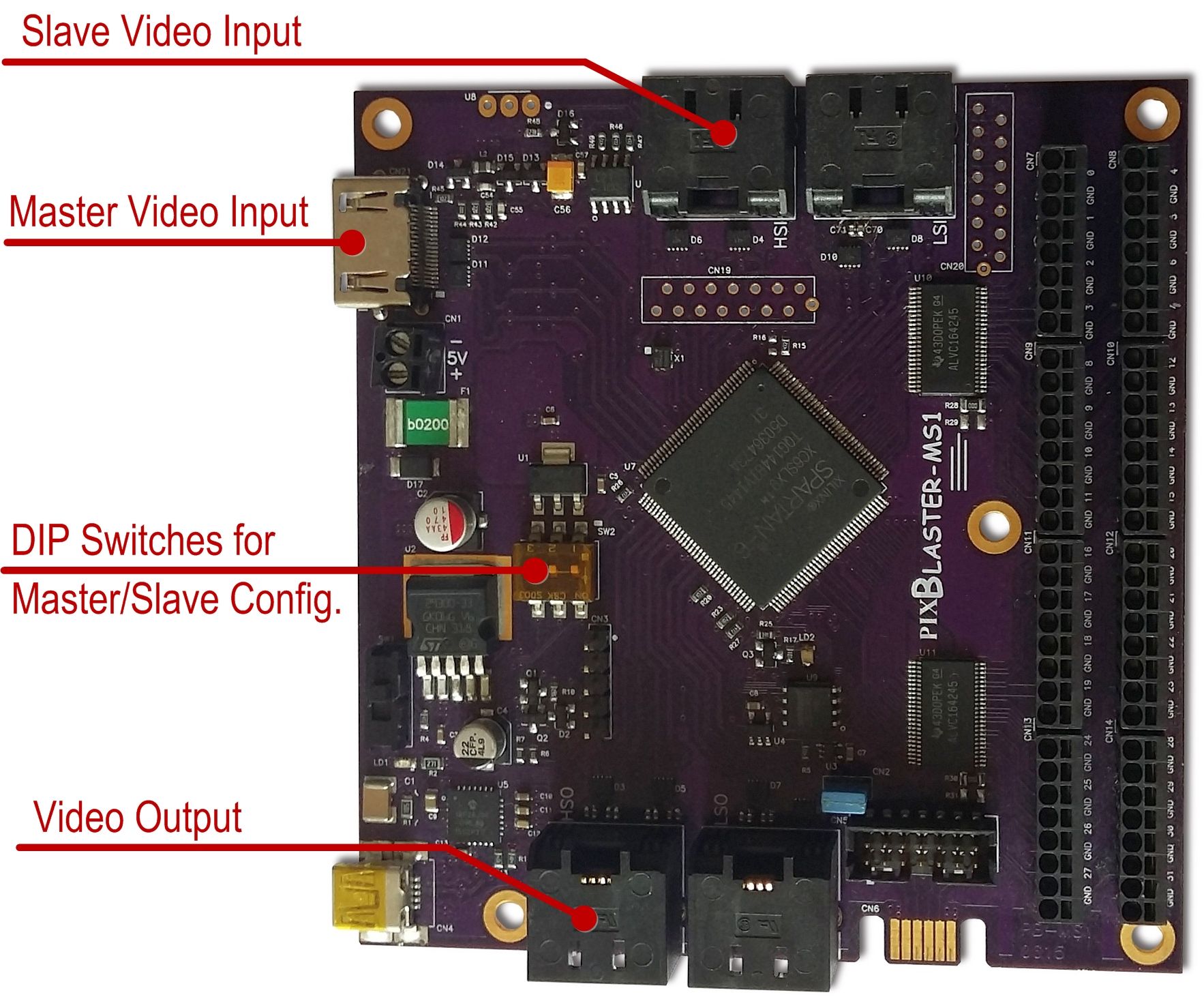
Each controller (2, 4) is configured for Master/Slave mode by on-board DIP switches. Other configuration parameters are setup only once for each board through a simple configuration menu on the PC (5) connected with the USB cable.
Display’s configuration parameters, such as LED timing parameters and the video input image part for display on the attached LEDs, are permanently stored in the on-board microcontroller that also controls the LED system’s boot-up.
Separate +5V DC power supplies, which are not shown in Figure 1, must provide sufficient power for the complete display.
* Full control link capabilities are TBD.
The Figure 2 explains video inputs and video outputs of the Pixblasters Video LED Controller. The Master Video Input should be used only on the first Pixblasters MS1 controller in the daisy chain. That board connects to the control computer by a monitor cable. DIP switches must be set for the Master FPGA configuration, as explained in the User’s Manual delivered with the board.
Slave boards in the Pixblasters daisy-chain do not use the Master Video Input. Instead, they receive the video signal through the Ethernet (STP) cable connected to the Slave Video Connector. Regardless of the configured Master/Slave mode, each Pixblasters MS1 controller sources video signal through the Video Output connector.
The following 2 min video clip explains how to connect Pixblasters MS1 controllers to support very big video LED displays.


