Project update 2 of 11
The SYZYGY Origin Story (Part I)
The SYZYGY standard was a response to customer demand for a flexible, well-defined, modern interface between an FPGA and off-the-shelf peripheral modules.
In the fourteen or so years that we (Opal Kelly) have been selling FPGA integration modules, we’ve sold tens of thousands of devices and spoken with hundreds of customers that have repeatedly asked us for commercial off-the-shelf (COTS) peripherals to help them even more. Ultimately, if a chip is available, engineers would often prefer to lean on COTS implementations as much as they can to accelerate development and minimize risk. The primary thing holding us back was the lack of an acceptable standard for the types of peripherals our customers needed. Digilent Pmods were great at the low end but the performance wouldn’t support the peripherals customers wanted. FMC / HSMC were great at the very high end but burned (wasted) too many FPGA pins to be useful. We needed something in the middle.
Understanding the Peripheral Space
Our first task was to make a list of all the types of devices we wanted to support. We included data acquisition (ADC, DAC) devices from low-speed precision to high-speed communication and everywhere in between. We included all types of image sensors, video I/O devices like HDMI and DisplayPort, and software-defined radio. We even included an assortment of sensors and robotics drivers. Basically, everything our customers were interested in went into the soup.
After we had this list, we mapped the requirements — pin counts, I/O standards, data rates, power supply requirements, and even device cost. All this data would eventually inform every decision for SYZYGY. We wanted to accommodate as broad a field as possible and to do this we needed to understand as much as possible about the design space in which these parts operated. A lot of these parts have evaluation boards from their respective manufacturers so we looked at those too.
SYZYGY
Several iterations later, we finally settled on SYZYGY:
- An open standard for high-performance peripheral connectivity
- Low cost, compact, high-performance connectors from Samtec
- Moderate pin count economizes available FPGA I/O and satisfies most device requirements
- SmartVIO to communicate power requirements from the peripheral to the carrier
- Cable options available at a reasonable cost
- FREE to license to encourage ecosystem expansion
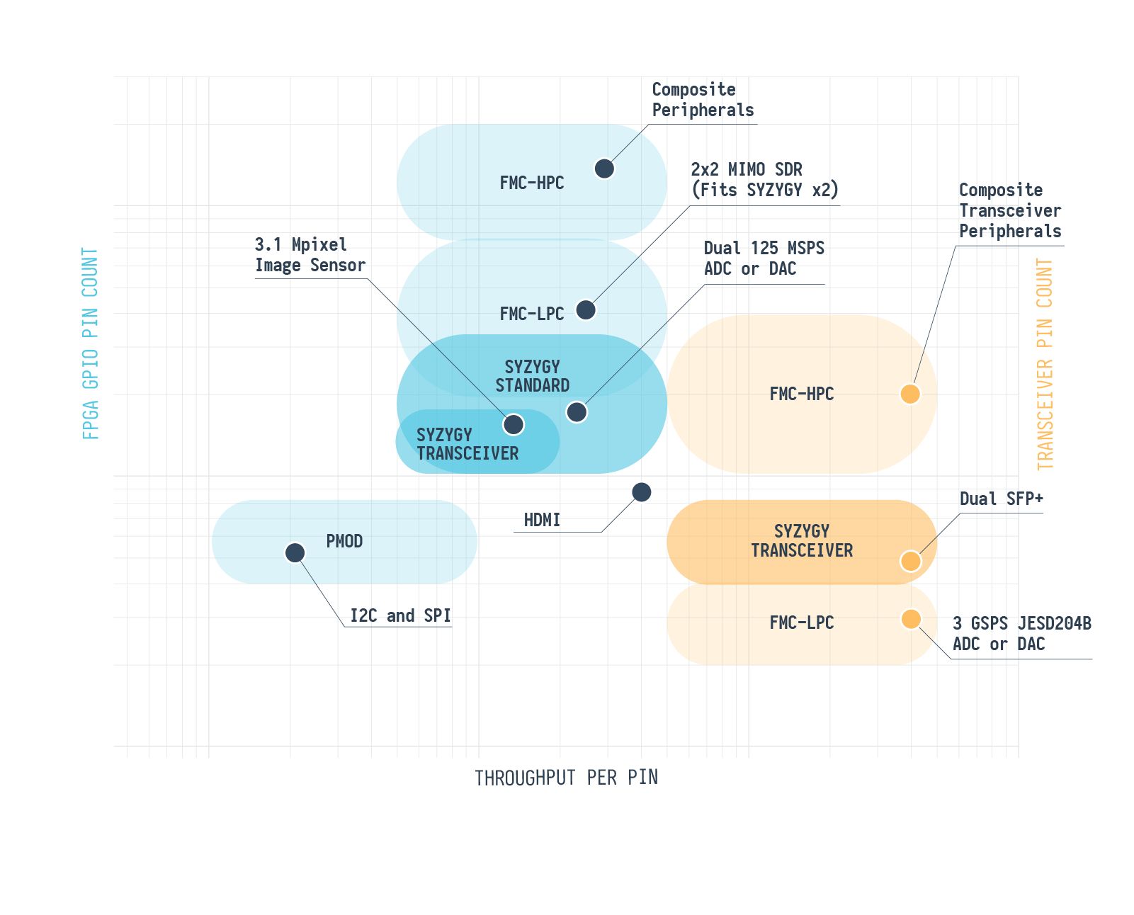
The chart below shows where Pmod, FMC, and SYZYGY fit together. There’s a lot to unpack here. See the description below to guide you through it.
The smaller dots represent specific peripherals (3.1 Mpixel image sensor) or possibly some smallish class of peripherals (I2C devices). The larger bubbles are a representative space for the corresponding interface standard. Lower per-pin throughput is on the left, higher per-pin throughput is on the right. Lower pin count is towards the bottom, higher pin count is towards the top.
Blue bubbles and dots are standard FPGA I/O. Things like CMOS, TTL, SSTL, and LVDS. Orange bubbles and dots are gigabit transceiver I/O. In all present and past generations of FPGAs, these pins are segregated so it made sense to classify them differently. You can’t use a CMOS pin for gigabit I/O and you can’t use a gigabit pin for CMOS I/O.
A peripheral standard can support any peripherals within its bubble along with those below and to the left of it.
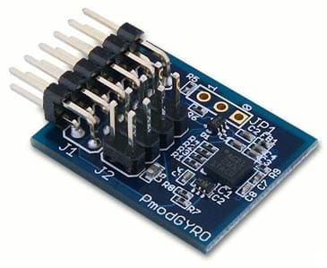
Pmod is a low-performance low pin-count standard that is great for I2C and SPI but it’s not very well suited to wider interface busses or high performance. It’s also very low cost which is very attractive to certain applications.
FMC has two pin count variations, LPC and HPC. Most of the pins on both connectors are designed for standard FPGA I/O. FMC also defines dedicated pins for transceiver I/O - ultra high performance I/O used for things like PCI Express.
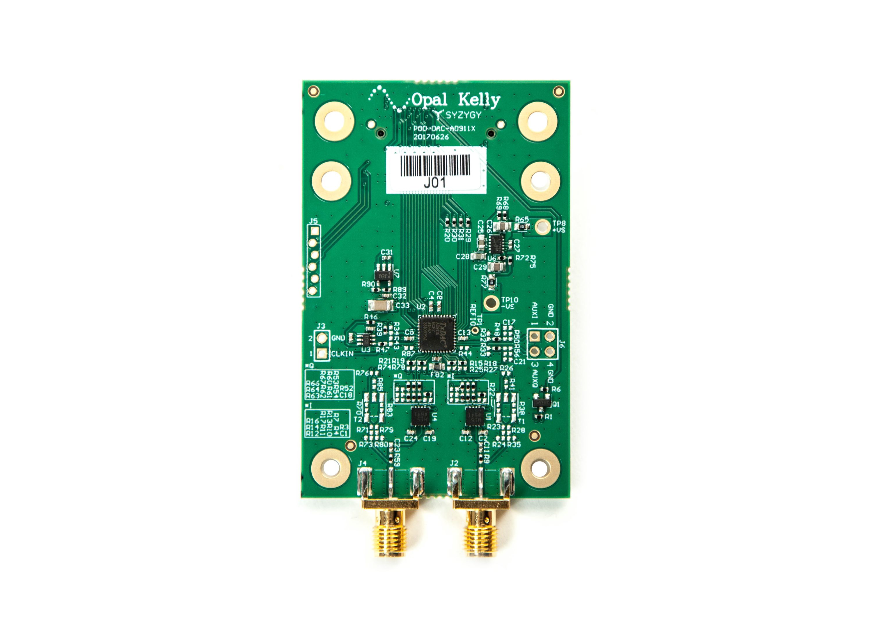
Like FMC, SYZYGY also defines two separate types of I/O. The first is the Standard connector that uses standard FPGA I/O pins. SYZYGY Standard peripherals get 28 I/O and two dedicated clock pairs that could also be used as I/O. The second is the Transceiver connector that is intended for transceiver peripherals. SYZYGY Transceiver peripherals get 18 standard FPGA I/O but they also get two gigabit receive pairs, two gigabit transmit pairs, and a reference clock pair for the transceiver.
In the next installment, we’ll talk about choosing the SYZYGY connectors.
You can download the full specification and read more about SYZYGY on SYZYGYfpga.io.


