Project update 7 of 11
Example SwarmDrive Firmware for BLDC Motor Commutation: Part II + Campaign Extension and Lower Price!
by Majodi PloegmakersExtending the campaign by 2 more weeks
First off, I would like to share with you that we have decided to extend the campaign for two more weeks. We need just a few more backers to get things going and I would like to send the last revision off to production as soon as possible so, as an extra incentive we decided to lower the price of SwarmDrive to $59!! I will keep you posted and explore some additional topics for my weekly update.
Example SwarmDrive Firmware for BLDC Motor Commutation: Part II
Last week in part I we covered the setup of the Space Vector LUT and obtaining the motor characteristics. In this second part we will look at the actual commutation code. So we know how many full signal cycles fit in one full physical turn of the motor.
For example, let’s say that the motor has five signal cycles for one turn:
Open loop commutation
What we can do now is homing the rotor to the zero position and then send consecutive LUT values to make it move X number of tiny steps. This is a form of open loop commutation, as we are not using the sensor to see where we landed exactly. By knowing the exact motor characteristics, we know where the rotor is after X number of steps.
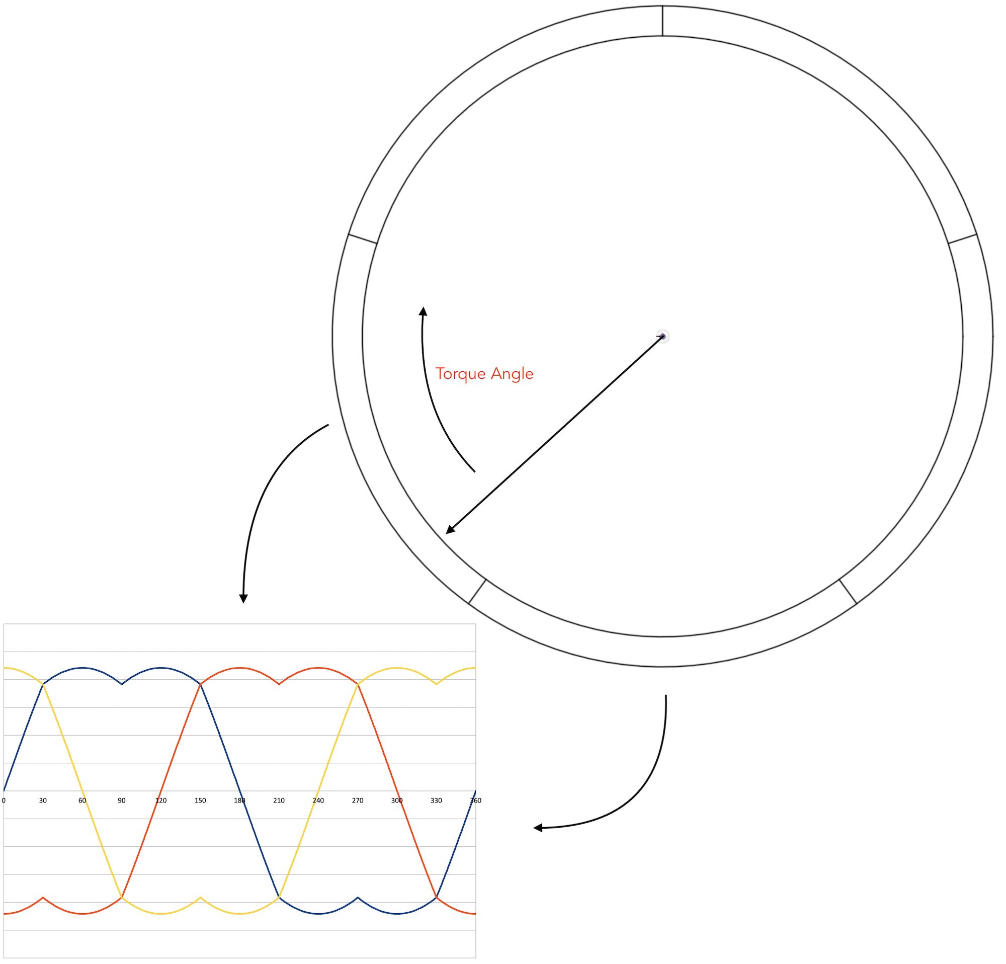
The speed of the motor depends on the stepping speed. So, a faster loop (less delay time) will move the rotor faster. But this has its limits. Also, the force acting on the rotor is mostly a holding force keeping it in a set position and just a tiny portion of the energy is used for movement on each step change. What we really want to do is to pull the rotor with the most effective force each time. The most effective force is not the pull to the next LUT step. It is a pull with a 90-degree angle (a number of steps ahead). This is the maximum torque angle. You can think of the carrot and stick analogy.
Closed loop commutation
For this to work we need to know the current angle of the rotor and then determine the next LUT position by adding a chosen torque angle (max 90-degrees). And as we are reading the sensor value each time it doesn’t matter how fast we do this (as long as the “carrot” keeps leading). But depending on the torque angle we use, the speed at which new values are set and the physical properties of the motor, at one time the rotor can surpass the “carrot”. When this happens, the motor will not run faster anymore.
So, we can control the speed of the motor by the speed at which new “goal” values are set and also, we can vary the acceleration by varying the torque angle. To accomplish a high commutation speed, we use a high-resolution hardware timer. createTimer will set up this hardware timer with a callback to run on each timer event. startTimer will start this timer with a certain interval.
Timer callback
The callback will first fetch the current physical motor angle and save this value to determine the delta between moves. This delta is used to calculate the current speed or RPM value. Raw sensor angle values are used here, and the code adjusts for zero crossing (where the raw angle value starts over after one turn). Also, there is a check for when the motor moves into the wrong direction. As it turns out the rotor can have trouble getting going at the beginning and this can even lead to minor movement in the wrong direction.
What we do next is determine the current signal angle by translating the physical angle to where exactly the rotor is in terms of signal steps (LUT position). To do so we use the signalRotationAngleR we determined with determineSignalRotationAngleR(), see part I. By using the modulus function, we can determine the fractional part of where we are within the current signal period. We then just have to add the number of torque steps:
    float currentSignalFraction = (float)(m->_angleR % m->_signalRotationAngleR) / m->_signalRotationAngleR;
    int goal = (int)((currentSignalFraction * SR) + m->_torqueSteps);
The new goal or step request is used to set the new coil duty cycle values using the commutate() method. This function simply adjusts for LUT array boundaries and then sets the duty cycle for each coil. Remember, the phase of the coils is shifted:
    int step = stepRequest >= SR ? stepRequest - SR : (stepRequest < 0 ? SR + stepRequest : stepRequest);
    if ((step >= SR) || step < 0) return;
    mcpwm_set_duty(MCPWM_UNIT_0, _coil0, MCPWM_OPR_A, ((float)_amplitude / 100) * _svpwm[step]);
    mcpwm_set_duty(MCPWM_UNIT_0, _coil1, MCPWM_OPR_A, ((float)_amplitude / 100) * _svpwm[step >= _phaseShift ? step - _phaseShift : step + _dblPhaseShift]);
    mcpwm_set_duty(MCPWM_UNIT_0, _coil2, MCPWM_OPR_A, ((float)_amplitude / 100) * _svpwm[step < _dblPhaseShift ? step + _phaseShift : step - _dblPhaseShift]);
That’s it in a nutshell. This will make the motor run smooth and reasonably fast. But I’m sure that there are many improvements possible. It all depends on what your application is. For instance, you could have an application for haptic feedback of a rotary encoder type of device. For that goal you don’t want the motor to spin at all, so you just play with the torque angle to generate a counter force. In other situations, you need super-fast spinning. That’s why having a console task on a separate thread to play with parameters comes in handy.
Until next time, Majodi

