Project update 3 of 12
Schematics now available!
by Mordecai RSOCORAD32 Electronics: Demystifying the schematics
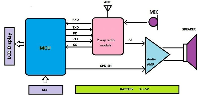
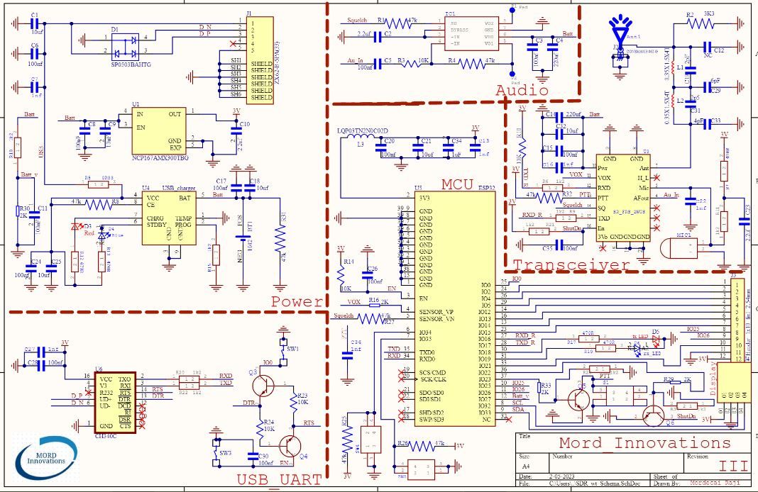
Here we have two schematics. A high level schematic, and a detailed one. The high level helps to get a quick grasp of how the subsystems are interconnected.
The detailed schematics shows…well, the details! These are available on our Github repository.
Building a customized version of SOCORAD32, or modifying the existing one requires a detailed understanding of the circuit diagram. Here’s some helpful facts about the board design:
Power management
The power management takes care of the tight tolerance of the components, and an on-board an intelligent battery charger is included. The ESP32 can also directly measure the battery level though a built-in simple resistor divider network.
Programmer
The programming interface is a simple USB to UART USB interface IC linked to the ESP32 MCU. This also includes a reset and enable button.
Audio amplifier
The heart of the amplifier is a low noise LM4871 from Texas Instruments. Audio input comes directly from the walkie talkie module and is also controlled by the walkie talkie module.
Transceiver
To ease understanding, I have labelled each pins in this module, in order to help the user to understand the functions of each pin, and why it is connected to certain components.
Display
The display is an OLED screen, controlled by I2C, which is driven by the MCU.
Antenna
Generally, any antenna of the frequency band 400 mhz - 470 mhz will be suitable, but the antenna we will be supplying is already tuned for maximum power transfer and reception. The antenna section in the schematics also includes a matching circuit which also acts as a low pass filter.
At a later date, we will release and discuss the firmware, which emulates a professional walkie talkie. This firmware will be more comprehensive than what we currently have in the repo, so stay tuned!


