Project update 4 of 7
Assembly Progress
Hello backers!
You’ll be soon holding the "Neosegment > Digit" modules in your hands. The 3D printed parts are ready, the PCBs are in the final stage of testing after which the only step left is to screw everything together!
In this update I’ll explain what I’ve been doing and what’s happening next. But first, here are some teasers:
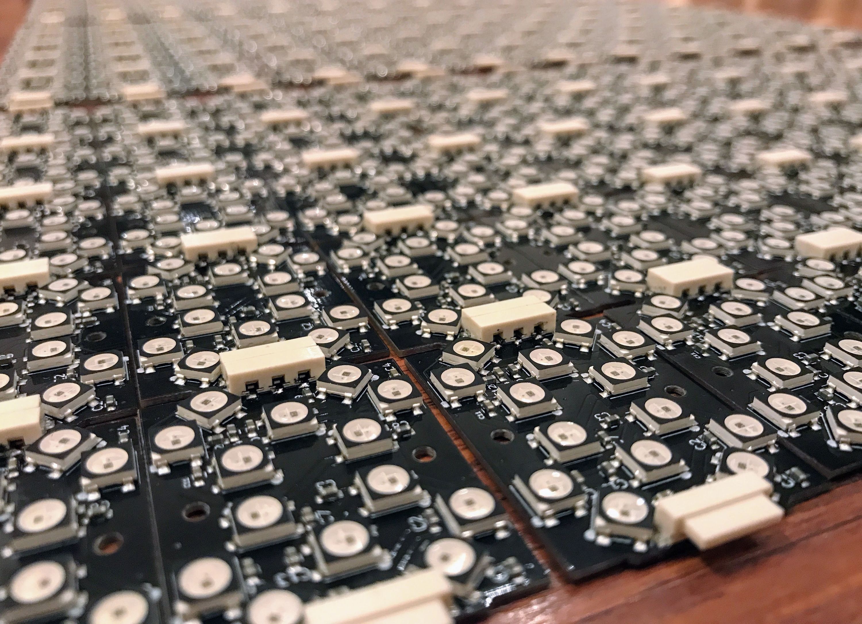
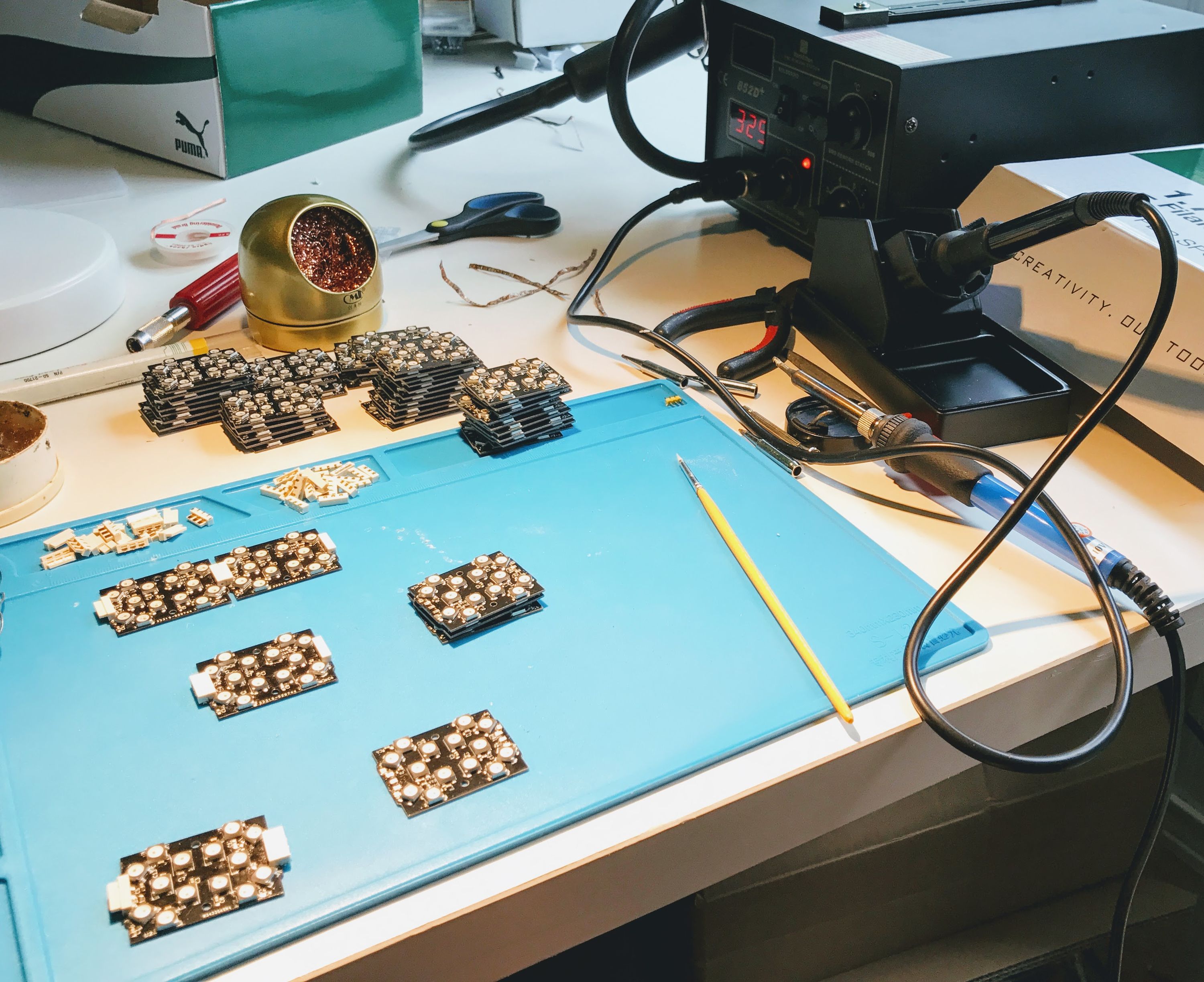
A couple hundred assembled Neosegment boards:

Testing of the assembled boards:
This week I’ve been fully invested into this project in a wide variety of ways:
- Reflow soldering a hundred boards
- Hand soldering six hundred connectors
- Cleaning the 3D printer's print bed between approximately 60 separate prints
- Checking each board's functionality and making sure that every single LED works correctly
- Coming up with test patterns and creating a simple way to test many boards at once
All that’s left to do is to screw all separate parts together and send the modules to Crowd Supply so that they can be distributed to you!
While the modules will be sent out to you on time, I’d like to highlight a couple problems that I ran into, and express my thoughts of how things could be done better for a similar project.
Problems encountered
The biggest problem that I’ve experienced so far is 3D printer speed and level of effort when it comes to getting a consistent output. Each Neosegment module contains 2 plastic pieces that are made of two different kinds of PLA plastic. The shell is made out of very high quality Carbon Fiber PLA plastic, while the insert is made out of regular PLA since its only function is to guide the light inside the modules. Switching the plastic at any point (when needed to print more inserts or more shells) introduced re-leveling the bed more often and loosing a lot of 3D printing momentum.
In retrospect, I wish I had bought one more 3D printer to keep the materials separately and to double my production output for plastic parts. This investment would’ve instantly helped me make more parts with minimal overlap and less wasted effort.
This might still happen if I get more orders for these modules and this should work just fine until I find a way to make plastic parts on bigger scale.
Another problem I’ve encountered was the speed of reflow soldering process. More specifically placing components onto the boards before they are soldered.
Each Neosegment module contains 29 parts (14 LEDs, 14 caps, 1 resistor) and without automated pick and place machine, it just takes a while to place all components on the boards before the boards are put in the reflow oven for Soldering.
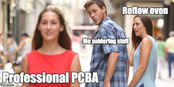
When I placed an order for PCB assembly of 200 boards at PCBWay, I didn’t expect them to be all perfect quality and was cautious not overspending money for something that might not work. Fortunately the boards came quickly and were amazing quality (only 1 board out of 200 had a defective LED, but parts were all placed precisely and soldered extremely well). In retrospect I wish I placed a bigger order at PCBWay and avoided doing as much of reflow soldering by myself. Of course I am saving money by not paying someone else to do the soldering, but after everything’s been done, I realized that my time was not spent well.
Basically, this is how I feel about it:
Anyway, if you’ve never done reflow oven soldering, I’ll explain what I had to do.
Reflow Oven Soldering Process
The reflow oven soldering process is widely used by makers when they need to make lots of circuit boards quickly. The process is simple and cheap enough, with very little generated waste. In short, it looks like this:
- Stainless steel or mylar stencil is created (via some service or powerful laser cutter, in my case it was done by PCBWay). The stencil contains holes for those areas where you need the solder.
- Special solder paste is applied to the bare circuit boards through the stencil, to only place the solder paste where it needs to be.
- The stencil is lifted up, leaving the boards with a thin layer of solder paste on the pads.
- Parts are placed onto the solder paste.
- The boards are placed in the reflow oven.
- Temperature profile is carefully chosen by reading the components' datasheets in order for parts to remain working after soldering.
- After setting correct temperature profile, the PCBs are baked in the reflow oven.
- When the baking process is complete, the PCBs are taken out and carefully inspected.
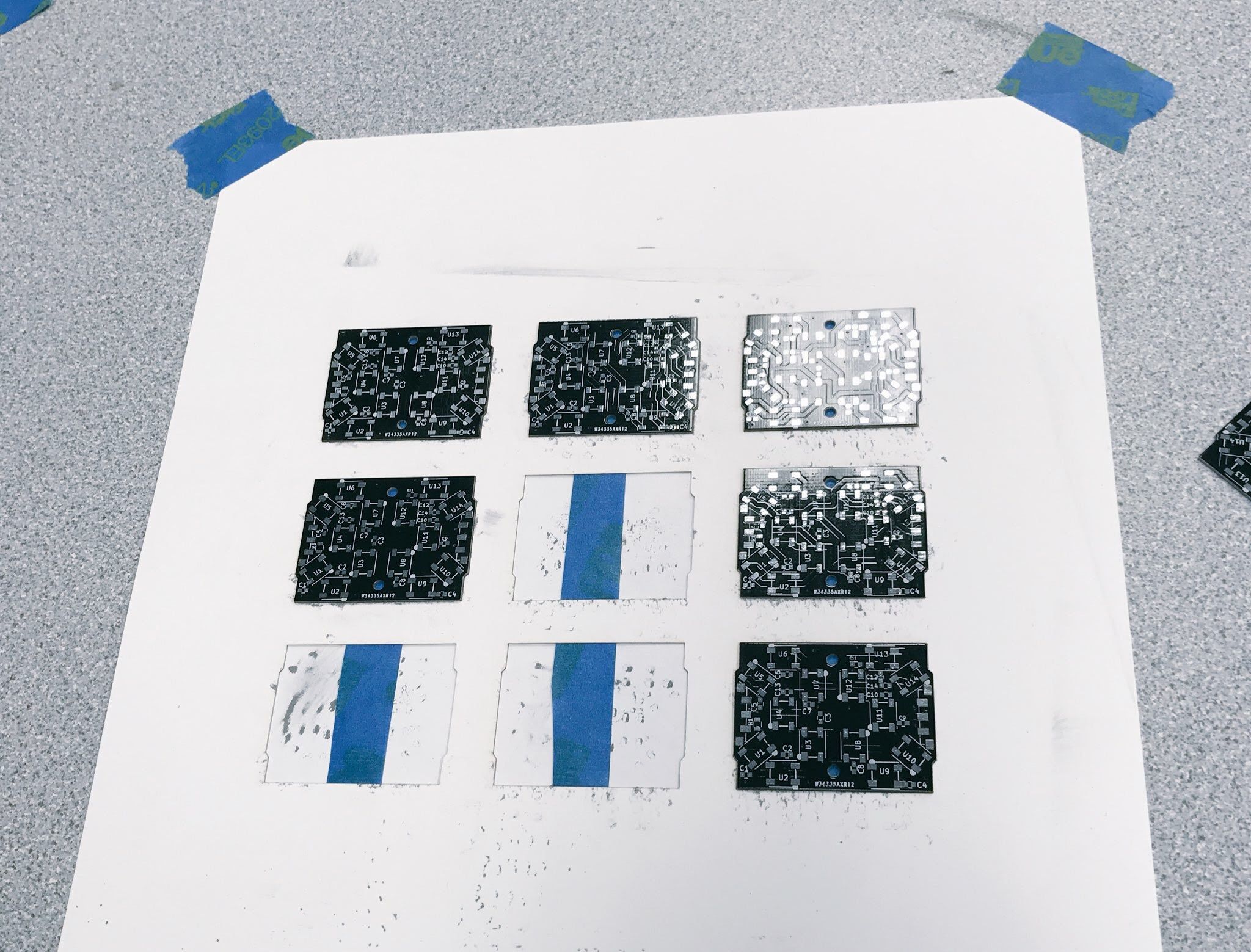
Because my PCBs were not panelized by design, I had to get a little creative in terms of applying the solder paste accurately. What I did was this:
- Exported board outlines from KiCad as an SVG file
- Laser cut that SVG file out of card stock so that each board just fits into the paper nicely
- Applied painter's tape on the back of the cardstock so that the boards are not lifted up by the tension forces of the solder paste after application
Here’s an image of what that looks like in action:

Then, the stainless steel stencil is put onto the boards, paste is squeezed onto the stencil and is evenly applied to the boards with a business card-sized piece of flexible plastic. After paste application, the stencil needs to be lifted up carefully so that the paste is not smudged on the boards. The result is this beautiful, even layer of solder paste:

Now, the boards need to be populated with components. Using tweezers, I had to put 29 * 100 = 2900 components by hand and that is by far the most time consuming part of the whole production so far. There are some automated ways of doing this, but the initial investment runs at about a thousand dollars for a machine like OpenPNP. So if I was making enough boards to offset that cost + time spent putting it all together, I would definitely consider making a machine like that.
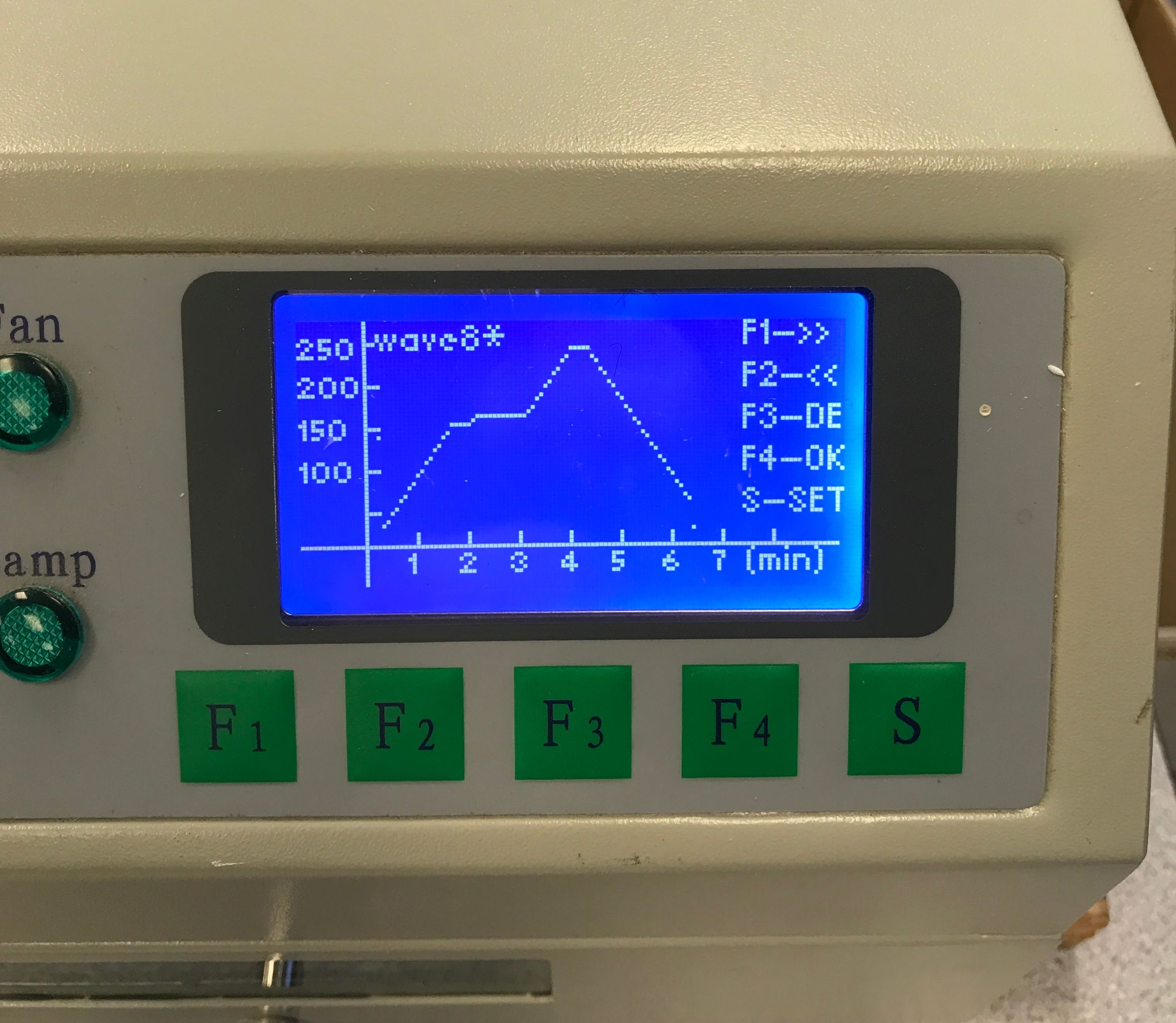
When the boards are populated, they can be put into the oven by the dozen and appropriate reflow profile can be chosen. Here’s the temperature profile that I used to solder WS2812B LEDs:
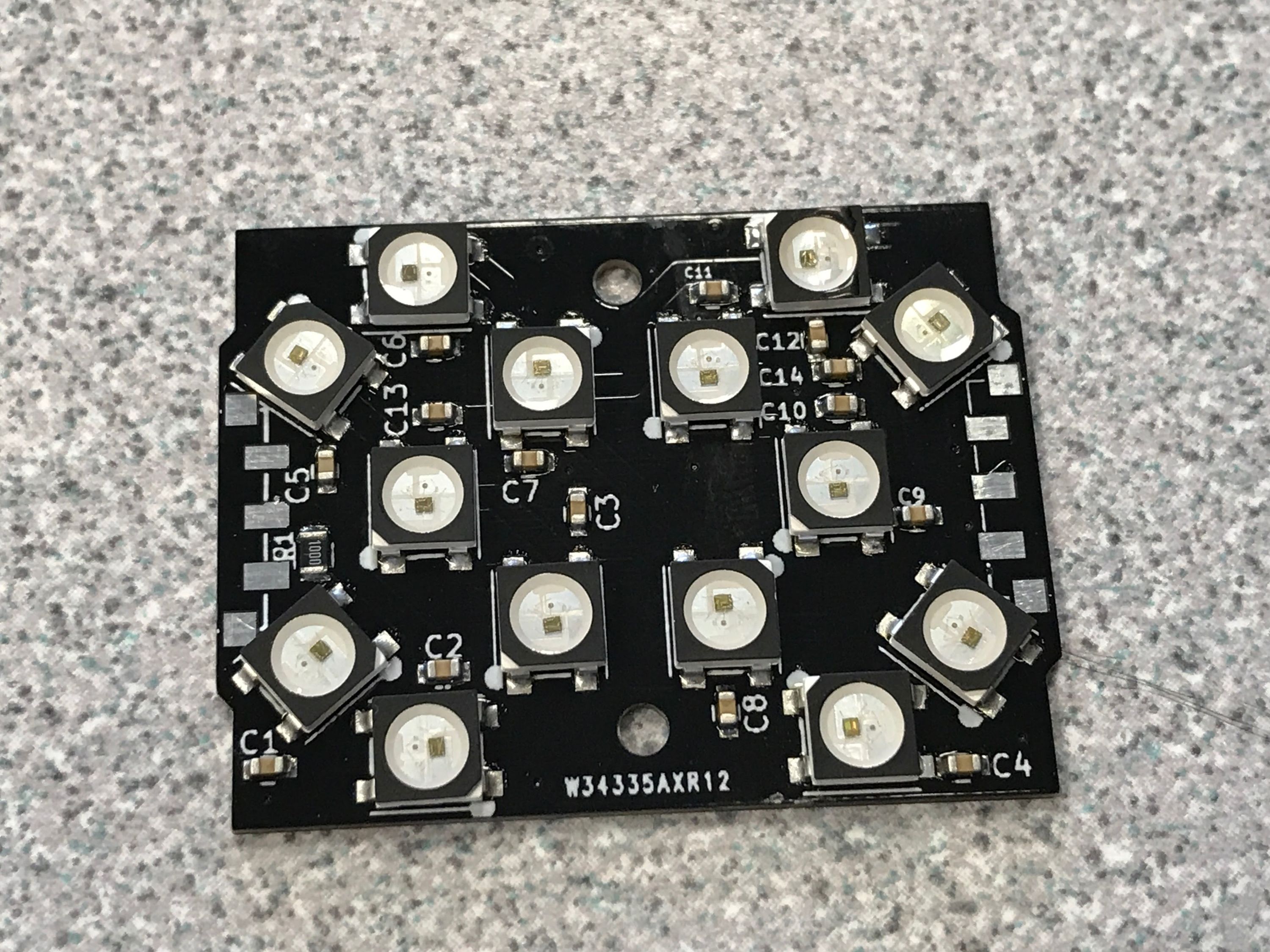
When the boards are done baking, they can come out and here’s what they look like, all soldered:

After the boards are soldered, I test every board and solder the connectors by hand to achieve precise positioning:
Lots of lessons were learned from the reflow soldering process and while I can do it over and over, I would want to hire someone to do this for me so that I can focus on other parts of the project.
Let’s get to 3D printing!
3D printing process
So far I have printed over 300 inserts and 300 shells for Neosegment. This is not really time consuming for me since the robot’s doing all the work, but it does require some setup and lots of patience to get things right.
I have been experimenting with various settings to get the most optimal print time while retaining great quality of the inserts and the shells. I settled on 0.16 mm height for the shell layers and 0.2 mm height for the inserts. The printing takes about 10 minutes for each shell and 10 minutes for each insert on my heavily upgraded Maker Select V2 printer. To reduce the number of times I need to clean and get the print bed ready, I print 16 inserts at once, or 12 shells at once. One simple observation that I already mentioned: if I had another printer, the production capacity would be easily doubled! I’m waiting for a deep discount on the same printer or for some good Samaritan to lend me one so that I can print out more plastic parts!
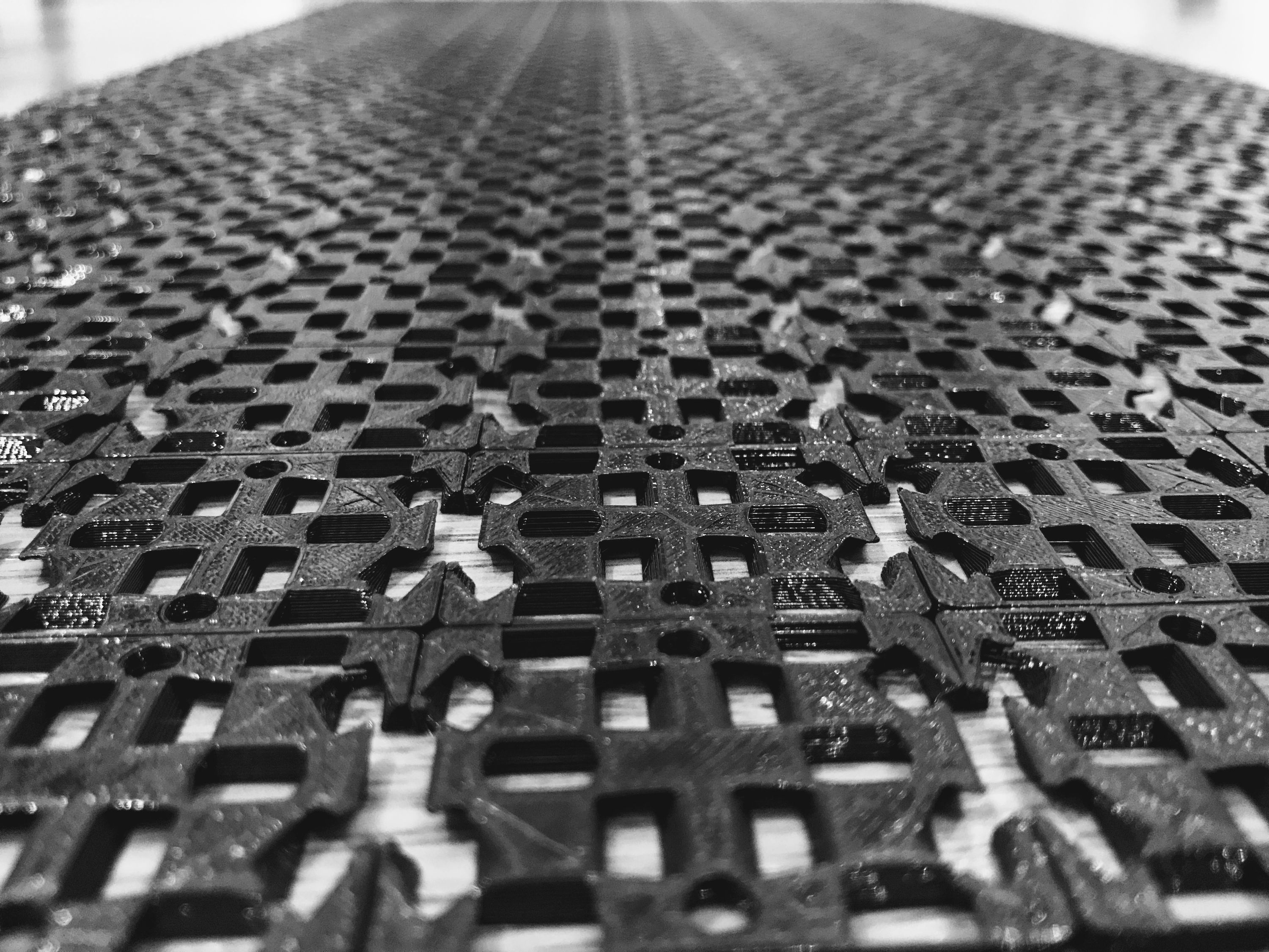
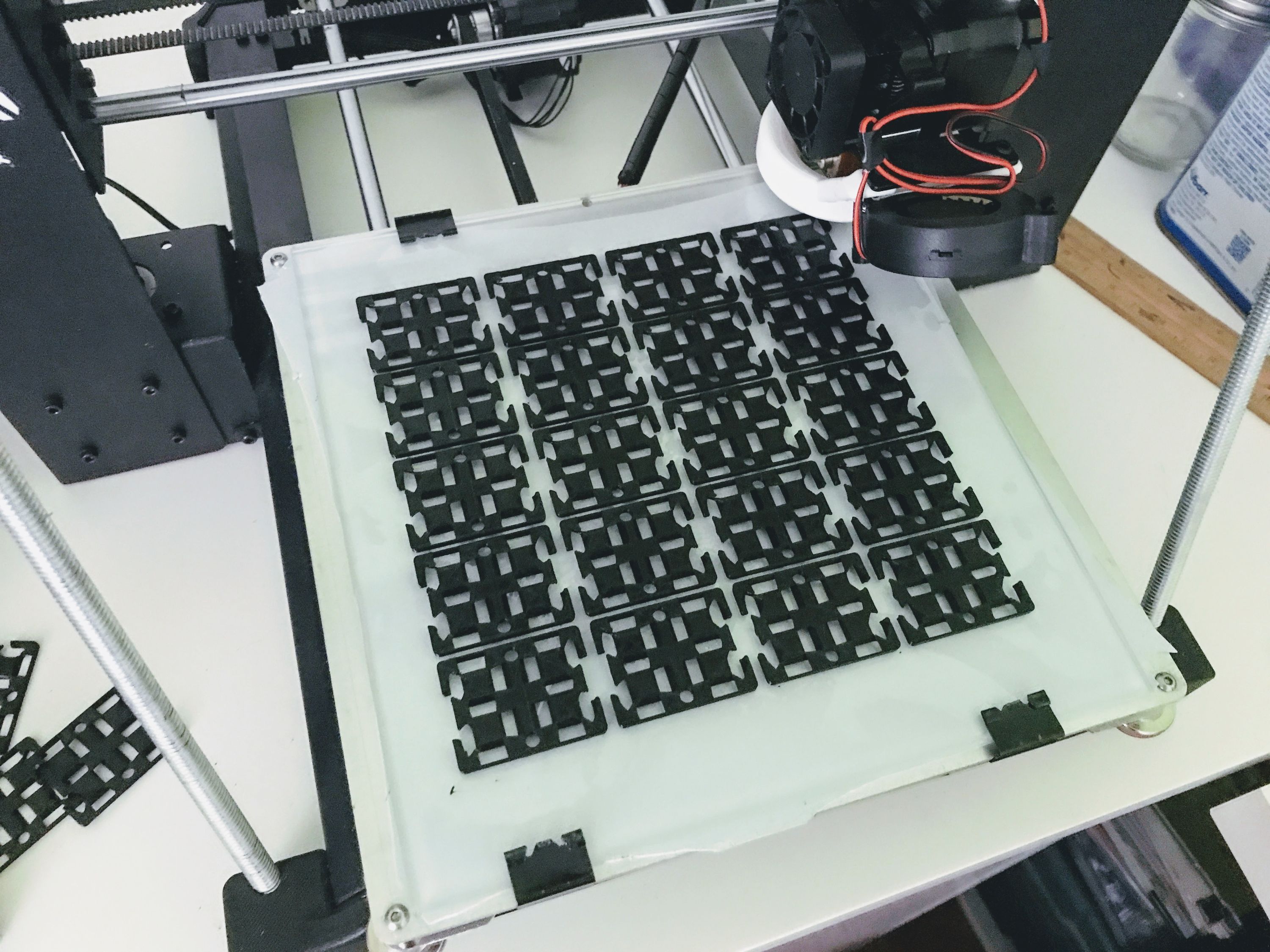
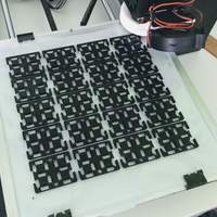
I’ll be shooting some timelapse videos of the parts being printed, but meanwhile here’s a picture of inserts being printed:

There are some additional upgrades I had to do on my printer to keep the process going. I’ve replaced the thermal padding under the glass on the print bed to have more even bed heating. I also replaced all fans with much quieter ones because the noise from the stock fans was becoming very distracting.
Next, shipping!
The parts are all ready for final assembly. I’ll put all modules together in the upcoming days and will send a nice box of Neosegment modules to Crowd Supply before September 15th!
See you then!