Project update 4 of 7
How the Video Circuit Works
by Adam ZHey Everyone,
The campaign is going great! We just hit $4,000 raised for the project and have started ordering some of the long-lead parts we’ll need for assembly. To follow up on the last update, which covered the audio system, this update will discuss how the video signals work.
Naturally, video is not a continuous medium, it’s a series of discrete frames. With NTSC video, roughly 30 frames are displayed per second. Before a frame is transmitted, say from the video header on the Raspberry Pi Zero or the composite video plug on a VCR, the transmitting device sends out a vertical sync pulse. This is a signal that basically says, "Hey, get ready because here comes a new frame".
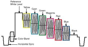
Next, to send each frame, the transmitter has to break it up into lines. This is accomplished by raster scanning across the image- imagine a camera that can only read one pixel of information at a time. Starting in the top-left corner of an image, begin scanning left-to-right, reading pixel values as you go. Once you get to the right side of the image, you’ve scanned one line of information. This line is encoded as signal in which the signal time corresponds to the location of the pixel and the amplitude corresponds to the intensity (black-to-white) value. Much like the vertical sync pulse, each line signal is preceded by a polite "ahem" called, you guessed it, the horizontal sync pulse. Once the last line is read, the transmitter moves onto a new frame and the process begins again with a new vertical sync pulse.
What about color? So far we only have intensity information ("Value," in a HSV color system). Color is achieved by adding something called the chrominance subcarrier. This is a modulation of the line intensity signal by carrier signal (3.58 MHz, for NTSC video). The phase of this signal controls the color ("Hue," in the HSV system) and the amplitude controls saturation (yep, the "Saturation" of HSV).
That’s a lot of information to digest, so perhaps this nice diagram of a signal from Extron will help. This signal would produce the standard colorbar test pattern you’ve undoubtedly seen before:
That’s all well and good, but how do we take such a signal and transmit it via radio? We can’t just take the signal, amplify it, and shove it into an antenna, all of the TV transmissions would pile up like a room full of people all trying to shout over one another. The signals also wouldn’t propagate very well due to their frequencies. Much in the same way audio is transmitted, we need to modulate the video signal with a carrier, which in the world of TV determines the channel you tune to. In such broadcasts, the video signal is amplitude-modulated (AM) by a carrier and the accompanying audio is frequency-modulated (FM) by an offset carrier frequency. In an NTSC system, the audio carrier is offset by 4.5 MHz.
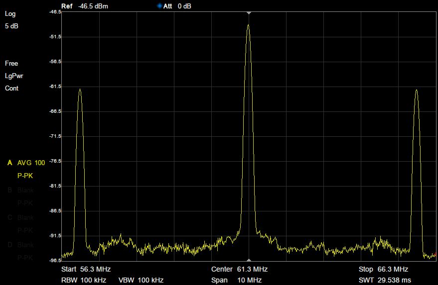
Here is the RF output of the PiMod Zero when examined with a spectrum analyzer. The tall peak in the center is the video signal centered at 61.25 MHz (Channel 3), and the two peaks offset 4.5MHz to each side are the audio signals.
When a TV receives such a signal, it demodulates it to extract the original video and audio signals and then displays/plays them accordingly.
Of course, the RF output of the PiMod Zero is quite weak, only milliwatts rather than the kilowatts a real broadcast station pumps out. This is because, unlike those high-power rigs, the signal is meant to be run directly into a TV rather than transmitted over long distances. Today most TV stations are digital anyway, making the old analog formats obsolete.
Alright, so this was a very quick introduction to how TV works (for a much better explanation, I wholeheartedly recommend Appendix I of the Art of Electronics). Even so, I hope this has been a helpful primer that illustrates how the composite video signal from a Raspberry Pi Zero can make its way onto your TV screen, with some help from the PiMod Zero.


