Project update 5 of 10
A Very Silly Tool for Assembling BeanCounters
by Nick PHello all,
We’re in the final stretch now and I’m getting very excited to build some widgets! In fact, I’ve been doing a lot of plotting lately about how best to approach the final assembly steps. Although I’m equipped for PCBA, I decided to partner with PCBWay to offload that portion of the assembly to their turn-key service. Likewise, I could have put together a printer farm to churn out the resin parts, but I have a dayjob, so I partnered with Wenext for the SLA printing. However, when it comes to final assembly, programming, QC, and finishing touches… I don’t trust anyone else. I want to get my hands on these things before they ship off to you folks, just so I know they’re ready for primetime. That means I need to have a workflow ready for when a few hundred PCBs and resin chassis show up at my door.
Each BeanCounter is held together with nine header pins which are soldered to the front and back PCB. These pins act both as rivets, holding the assembly together, and as conductors, providing power to the IR emitters on the underside of the top board. I really like this solution, but it has two flaws: It can be a little finicky to get these pins into place, and I don’t think I can actually buy the pins. Currently, I’m removing each pin from a strip of pin-headers and simply discarding the plastic bit. Obviously, somewhere in the world there is a big loose bin of these pins ready to receive the plastic bit that holds them together, but I’ve never seen that thing for sale. So I began to think about what I might do to avoid painstakingly disassembling a bunch of pin headers with a pair of pliers.
My first idea was to do away with the metal pins altogether and simoply use wire. Proper solid wire would work just as well as the metal pins, but could simply be purchased in reels and then straightened and cut to length. This train of thought quickly devolved into designing a jig that would allow wire to be fed into a BeanCounter assembly, soldered on one side, tensioned, and then soldered on the other before being trimmed. This way, the straightening and trimming operations would be part of the assembly workflow. However, the design of this jig was getting far too complex. After a certain point, it wasn’t going to save any labor, it was just going to become a new thing to troubleshoot.
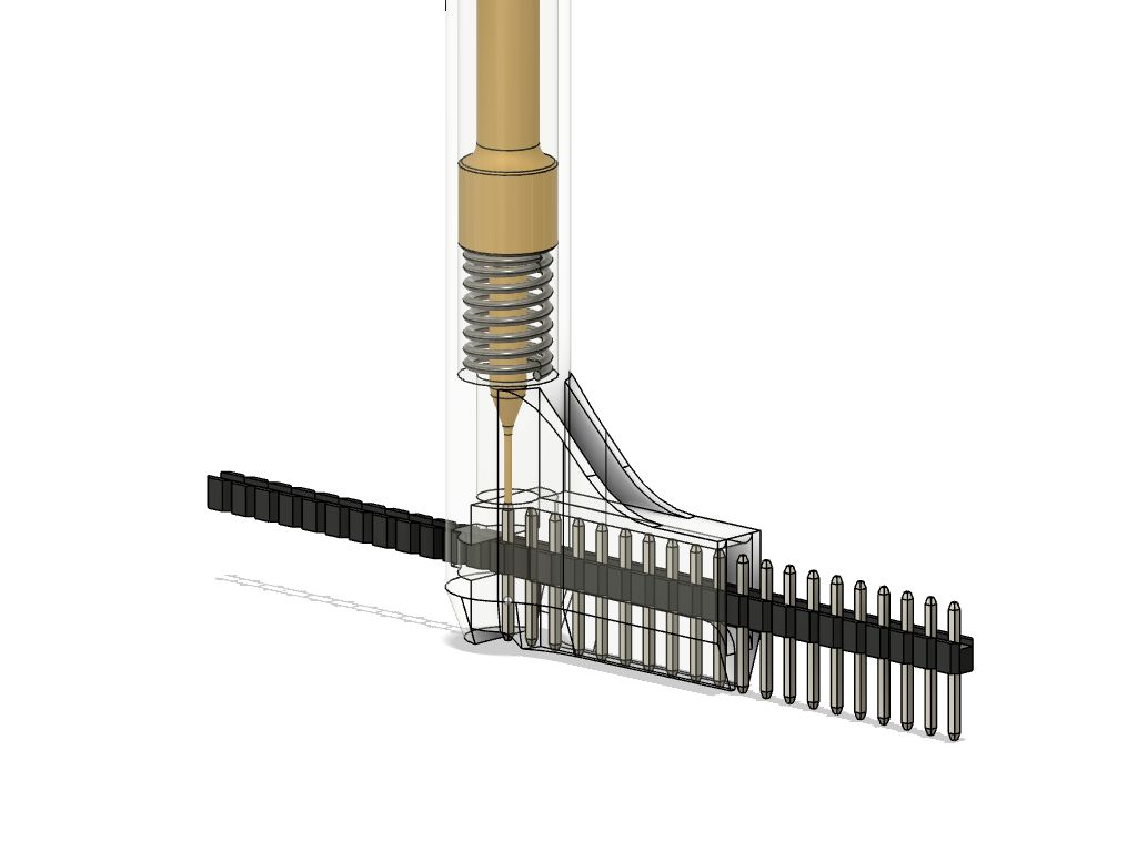
A better idea is to assume I can procure the metal pins and create a 3D-printed jig that clamps the BeanCounter assembly together while preventing the pins from dropping all the way through during soldering. This way, I just need to stack the three subassemblies in the jig, clamp it, drop in the pins, solder nine joints, flip, solder nine joints. If I’m really clever, this jig might even have a 6-pin ISP pogo connector to program the unit during assembly. This is a pretty reasonable solution but it still involves picking up little metal pins with tweezers and dropping them into holes… I can already feel the repetitive stress injury. That’s when I had a new idea. What if I could solve two problems at once: separate the pins from the plastic strip and dispense them ergonomically? What if I could treat a strip of pin headers like a strip of brad nails? So I popped open Fusion 360 and I started sketching this:
Isn’t it wonderfully silly? Imagine a retractable ballpoint pen, but when you click the top you don’t get a pen at all. Instead, you push a metal pin off of the strip and out of the end of the tool. Obviously this is a tool with extremely limited application, and it’s currently incomplete, but I think I’m going to see it through. It could save me a lot of time and hand strain but—honestly—it’s just too funny not to build.

