Project update 10 of 20
Production Planning and Nearing Third Stretch Goal
As we get close to the final week of the campaign, I’d like to briefly let you know what has recently been keeping us busy.
Updated PCBs
All changes that were mentioned as a part of stretch goals #1 and #2 are now included in the latest PCB revision that are now available on GitHub as version r5B12. The Arduino shield board has been updated to include the incremental encoder with switch, and the AUX power module is now equipped with a digitally controlled power relay.
We took this opportunity also to completely isolate cooling fan power from the rest of the system to reduce EMI. Furthermore, as an upgrade path to an even more attractive GUI in the future, we added support to the Arduino shield board for a 3.5” Riverdi TFT touchscreen display equipped with the FT80x controller.
Precision
I conducted some testing of mV/mA resolution that is especially interesting for limiting output current. It is currently possible even when the resolution in firmware is set to the default of two digits (i.e., 10 mV, 10 mA) when you want to set value below 1 V or 1 A but measured values will be rounded to tens of mV, mA. Changing value display resolution to three digits is already possible but we have to allow entering of more then two digits and would like to optimize a little displaying of all that digits to use higher resolution only where it’s necessary (e.g. it’s utter nonsense to display temperature measured on sensor with three decimal places when only round number is more then enough!).
Preparation for Stretch Goal #3
Since it seems that we are approaching Stretch goal #3, the power board has also been redesigned to provide a second current range (0–500 mA) in addition to the existing range (0–5 A). The new PCB prototypes are ordered so I can check in practice that it will behave as expected.
Updated Enclosure Panels
We’ve agreed on the new customized enclosure with our enclosure manufacturing partner, Varisom (Portugal). New prototypes incorporating the modified front and rear panels should be ready next week. An updated 3D model is now available (requires Acrobat reader).
Box Samples
Last week I visited local manufacturer of cardboard boxes (Kartonaza) and discussed with them a new box that should ensure simple but safe packaging of all components. I’m expecting box samples in coming days.
Firmware Updates
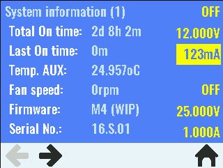
On the firmware side we are approaching finalization of version M4 — we’ve added a triggering subsystem to set output values in accordance with some external event (e.g., push of the encoder switch button, receipt of a SCPI command, or state changes on the digital input available on the front panel push-in connector). Martin continued to work on development of so-called arbitrary waveform generator functionality, and for that a SD card (that is now a standard part of the solution thanks to Stretch Goal #2) will be used to store an almost unlimited number of output voltage and current patterns. Of course the same SD card will be used for data logging in the future.

