Project update 24 of 24
Latest Firmware *1.7* Released and a Note for Two-Channel BB3 users
by DenisWe are pleased to announce that BB3 firmware version 1.7 has been released. As before, you can find instructions for the firmware upgrade in Chapter 13 of the user manual.
In this version, 42 published issues (fixes and improvements) have been resolved, thanks in large part to your feedback and suggestions. We would highlight the following features:
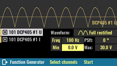
Simple function generator that can be activated on power modules (DCP and DCM) as well as on SMX and MIO. One of the interesting options is the ability to generate half- and fully-rectified waveforms on a DCP module. This can be used to simulate rectified AC mains for testing the final stage of a power supply, battery charger, etc. Set voltage to go up to 80 V and current up to 10 A if two coupled DCP modules are used.
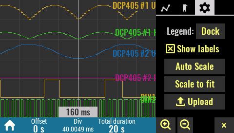
Modified Data logger (DLOG) that now accepts more than four signals, sampling speeds over 1 KSPS and operation with mixed signals (analog and digital). Furthermore, it is now possible to insert bookmarks (via PC or UART port on the front panel) using SCPI commands during data logging.
UART support: it is now possible to communicate with BB3 via the DIN1/DOUT1 pins on the front panel. Three modes are supported: Buffer, SCPI, and Bookmark. In SCPI mode, it is possible for an external device (another BB3 or D.U.T.) to directly control the BB3 using supported SCPI commands.
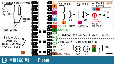
Pinout page: the module info page now contains a Pinout page showing the module terminals as well as all resource numbers. This can simplify SCPI programming.
Updated versions of the English User Manual and the SCPI reference guide are also now available and include changes introduced by firmware v1.7.
Unfortunately the German version of the User Manual is not yet synchronized with this firmware version because we no longer have a person available to do so (If anyone is interested, please feel free to contact us).
Note to owners of the two-channel BB3 kit
Finally, one note to owners of the two-channel BB3 kit, i.e., all those who have two Mean Well LRS-150F-48s to power DCP or DCM modules. It turns out when the two Mean Well’s are turned on, they put extra stress on the circuit that controls their AC power input. The end result can be overheating of the R4 power resistor (only the AUX-PS module r3B3, green PCB is affected!). As a remedy for this, it proved sufficient to install an X2 capacitor in parallel to the AC input of one of the Mean Wells. The value does not seem to be critical, as the problem is solved using a 0.47 uF cap as well as a 4.7 uF we tried.
This problem has been reported and explained on GitHub as #108.


