Project update 4 of 9
Fully Funded! Now What?
by Aleksa BHi Everyone,
First of all, thank you so much! I’m blown away by all of your support and it was a huge relief getting past our goal so quickly! I don’t take the trust you’ve put in my project lightly and I am dead set on delivering without delays, so I’ve decided to work on ThunderScope full-time at least until all the orders are fulfilled. In this update, I’ll talk about my game plan for the hardware and some work I’ve done on it these past few days.
Hardware Game Plan
Prove out as many changes on the existing Rev 4.1 (Beta 2) units as possible. I have been doing this over the course of the front end video series. Expect a new video soon on the latest fixes that got us down to our impressive noise performance.
Send out Rev 5 front end test boards to prove all the changes that cannot be easily added to the existing boards.
Design and hand-build three Rev 5 (Gamma 1 – Developer Edition release candidate) ThunderScopes.
Iterate if necessary – may need a minor up-rev before production. I did the same thing for Beta, hand building Rev 4 (Beta 1) and sending out Rev 4.1 (Beta 2) to a local CM to build a dozen.
Thoroughly bake and test inventory of HMCAD1520 ADCs. I have bought some older parts during the chip shortage that have been prone to failure during soldering, probably due to moisture ingress and thermal shock. We found this out during the Beta 2 run at the local CM.
Arrange for the run of 50 Developer Edition units to be built at Entropic Engineering. They’ll show me how to work the PnP, I’m very excited :)
Testing, calibration, and box build, design fixtures based on lessons learned.
Scale up for the remaining batches – this is easy right?
Progress This Week
First up, there’s one last noise issue left that only shows up with a disconnected input (left) and disappears with a shorted input (right). Andrew Zonenberg (screenshots are from his TS Beta unit) found this one and tracked it down to the FPGA 1V0 rail. This 5 kHz load transient makes its way to the main 3V3 rail and into the input signal!
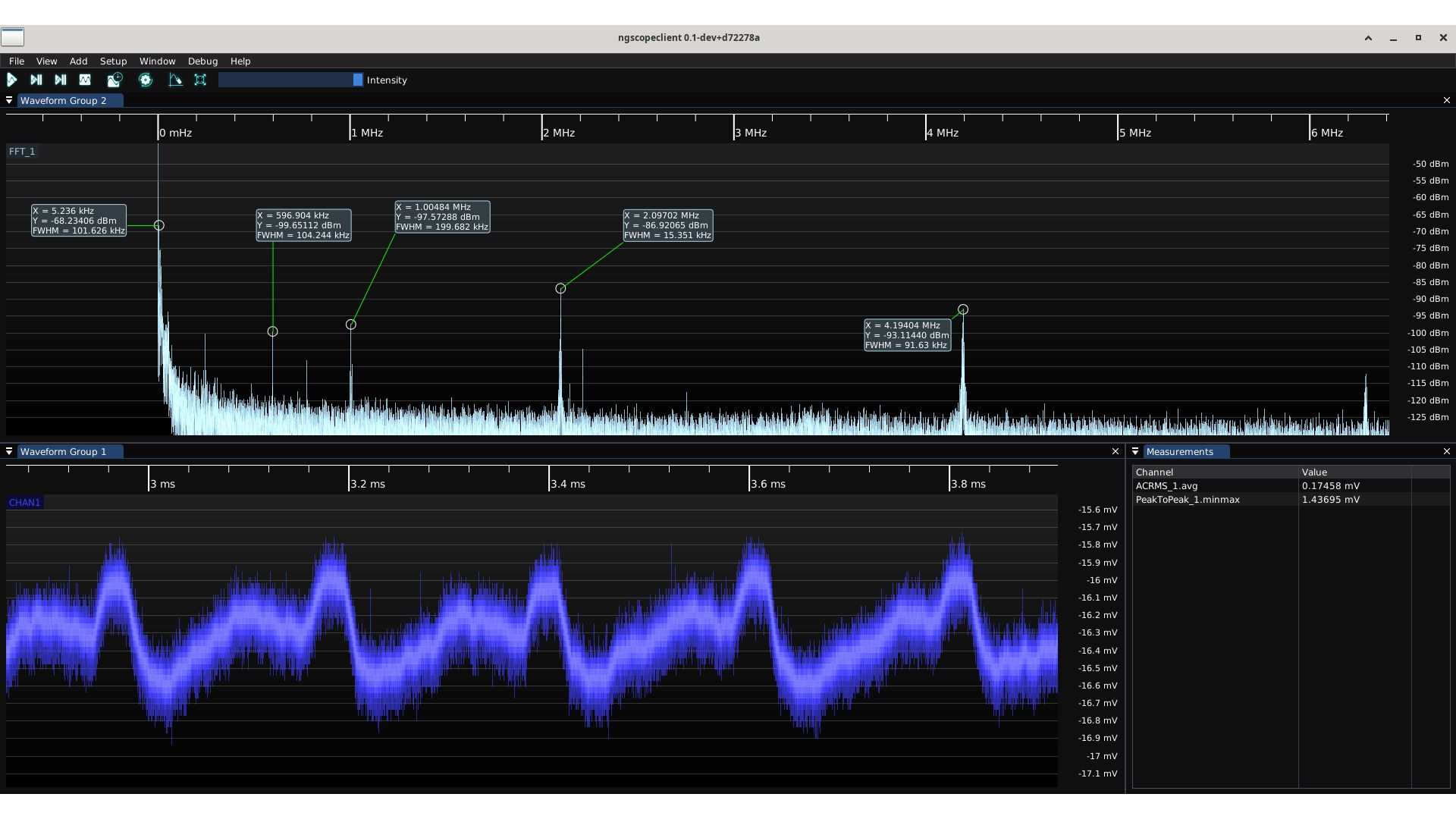
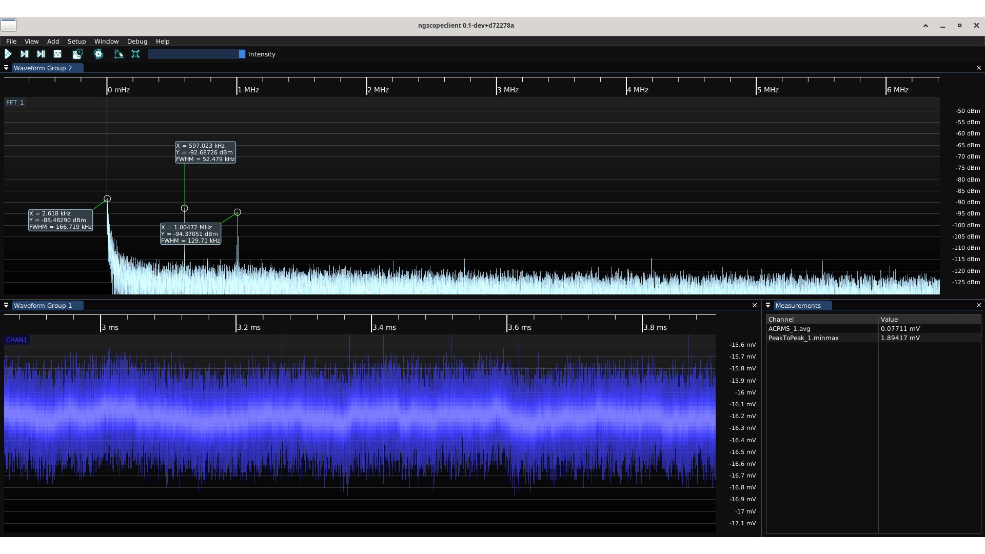
Since we are using 3V3 provided off-board (from your motherboard or from a USB4 adapter), we don’t have much control over the regulator’s transient response. So the solution is to make this rail ourselves! We currently use a load switch to turn this rail on at the appropriate time, but if we depopulate it and solder a bodge board on the other side, we can add a buck regulator to generate this rail instead.
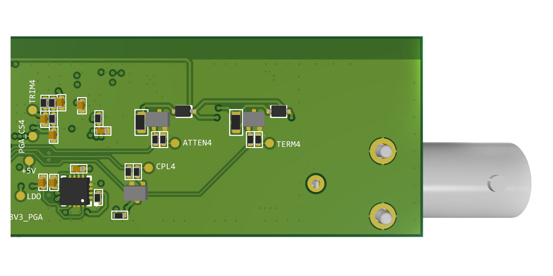
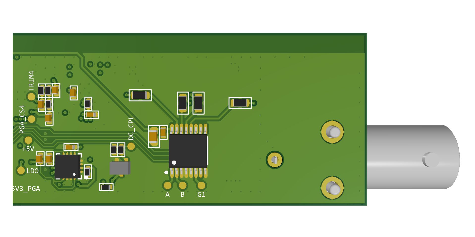
Rev Five Front End Test Board
There are a few improvements I wanted to test for Rev 5, like using a super stable voltage reference for the bias voltage and replacing a manual calibration potentiometer with a digital one (one less manufacturing step!). But the biggest mystery was how the noise on the 3V3 rail was even getting into the front end.
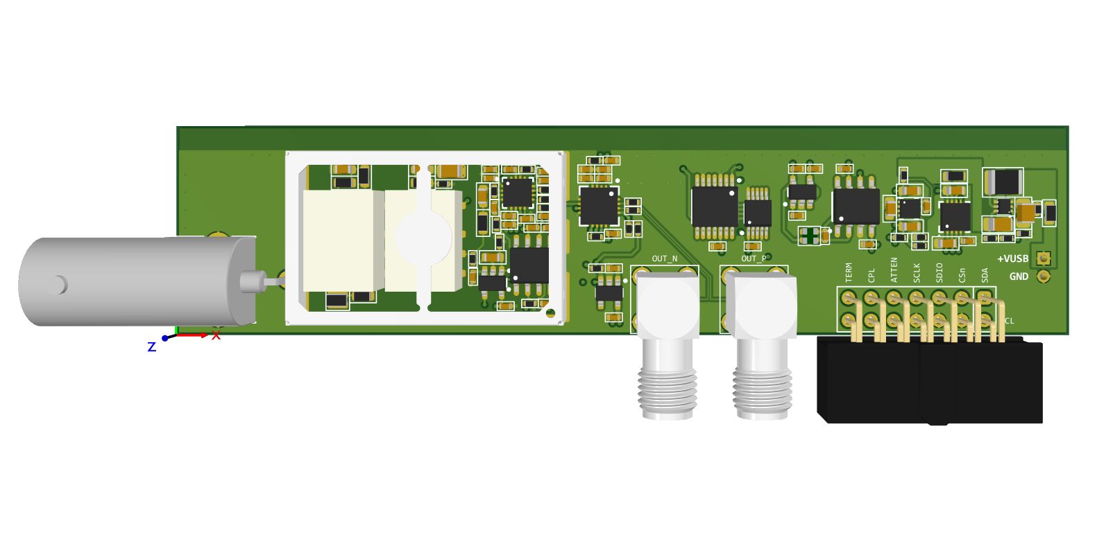
Our best theory is that it’s coupling through the relay coil, which is being energized with the noisy 3V3 rail! I’ve released two test boards to test this theory, both identical except for the relays. The first board uses the same relays we always used, while the second uses latching relays. These latching relays only need to be energized for 10 ms or so before they hold their state and no longer require a voltage at the coil. Neat, eh? There is one drawback, you need both positive (set) and negative (reset) voltage across the coil, making them harder to drive. Typically an H-bridge configuration is used to drive these, however I needed something more cost and IO efficient. I found the CD74AC238 decoder to be a great fit, requiring no extra IO when used to drive four relays (two channels), nor extra diodes to protect it.
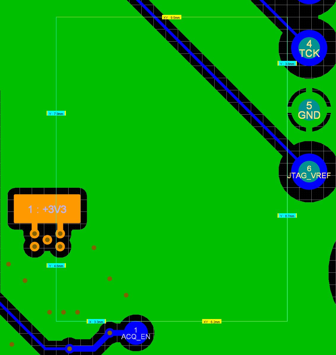
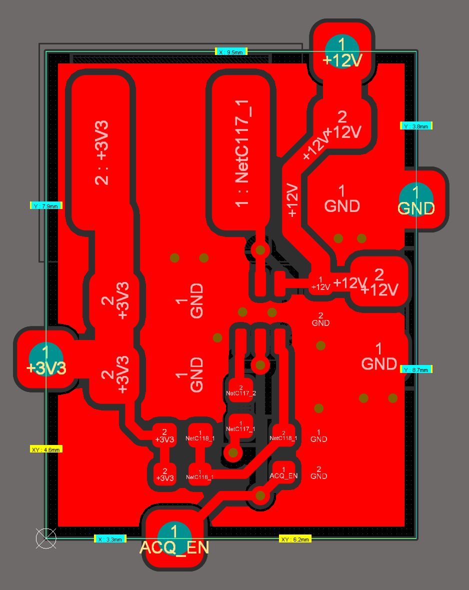
HMCAD1520 Impedance Tester
As mentioned in the game plan above, I have to test my inventory of HMCAD1520s after baking them for a long time to make sure they’re ready for production. This will be a two step binning process. First, I will check the impedance of the voltage rails, as the most common failure mode for these is to develop a short across one of the rails and ground. Then I will run them through a functional test, basically putting the chip into a fixture that looks like half of a ThunderScope to make sure it’s sampling correctly and sending out the right data. I’ve designed the fixture for the first step in KiCad to start re-gaining some familiarity for the eventual migration of all ThunderScope design files.
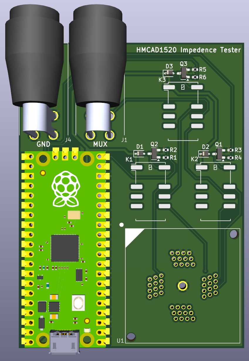
That weird footprint on the bottom right is a test socket for QFN-48 parts with exposed pads (3M part number 248-5205-01). You just connect a multi-meter, put the part in the socket, and run the test script to measure all the voltage rails! I’ll put the script up on GitHub once I get the fixture up and running.
And that’s it from me this week, still lots to do behind the scenes and even more work being done on the software side by the community. If you have any more questions send us a message using the "Ask a question" link on the campaign page and/or join our Discord server, where we coordinate most of the development for the project. Hope to see you soon for another update next week!
-Aleksa