Project update 7 of 11
Design Modifications and Improved RF Performance
by Jaydeep DHi everyone,
It’s been a while since we posted an update. Nevertheless, we have more exciting news to share.
To begin with, after the campaign we analyzed the design and made improvements in the following areas:
Design Modification for EMC compliance
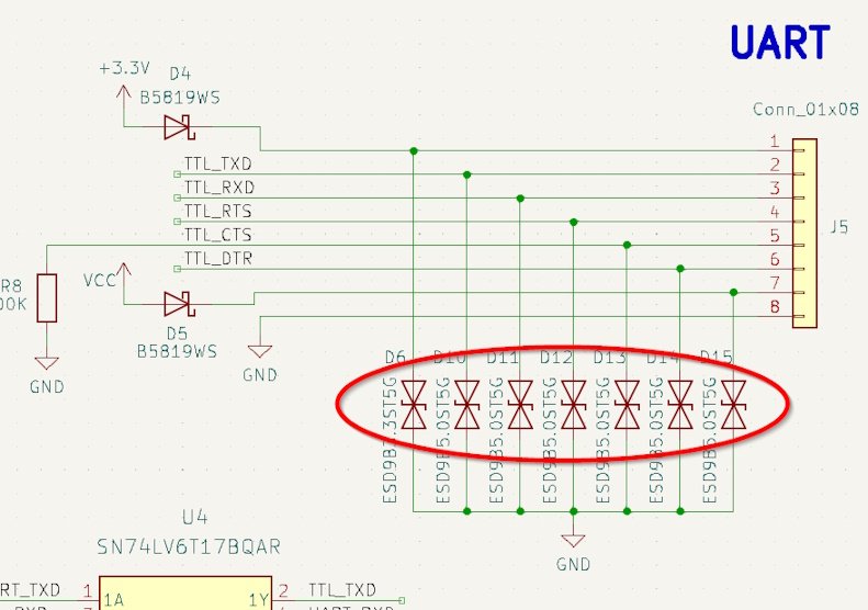
ESD testing is part of the EMC tests carried out on the device. To ensure ESD suppression, we have added ESD protection diodes on each header pin.
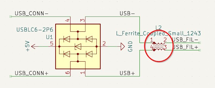
For the USB port, we had already used an ESD protection diode array in the previous design, which will take care of ESD voltage spikes. Additionally, we have put a common mode choke coil on the USB lines to suppress any noise on the USB differential lines.
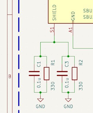
To further enhance EMI performance and ESD protection, we have added an RC network between the shield and ground of the USB on both WiSer-USB and WiSer-TTL, taking inspiration from Microchip’s application note on USB devices.
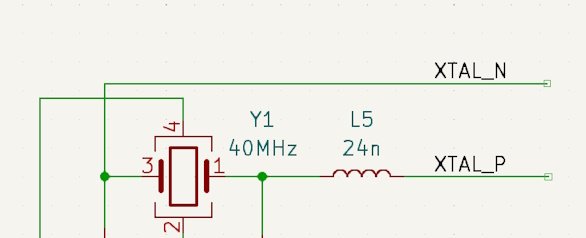
Another significant improvement we made in the design is the use of a 24nH inductor on the crystal pin to suppress harmonics.
Improved RF performance and range
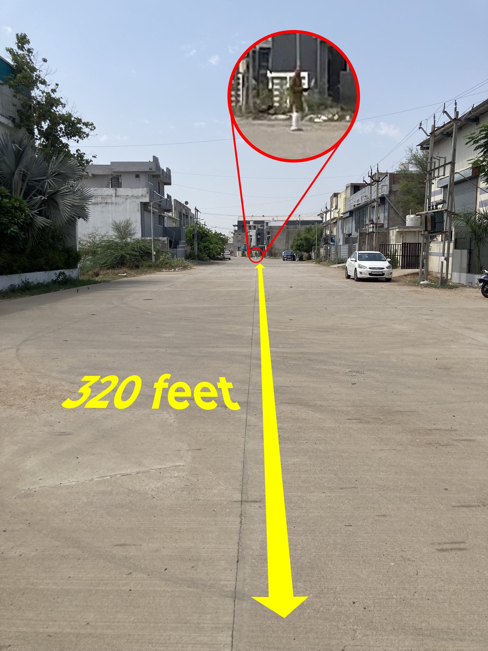
To improve RF performance, we switched to a higher gain chip antenna and, after consulting the antenna manufacturer, we increased the ground clearance around the antenna and overall ground area. These changes helped achieve better RF range. We tested the RF range outdoors using our typical testing method described in detail here. The RF range has significantly improved from 65 feet to 320 feet. The photo below shows the actual outdoor testing and the distance between the WiSer devices.
All the above changes were made possible by slightly increasing the size of the WiSer-USB (43 x 21.5 x 8.5 mm, with enclosure) and WiSer-TTL (38.5 x 39.5 x 10.5 mm, with enclosure). The latest hardware files are available on Github.
Another update we want to share is that we have booked EMC testing slots for the first week of June at a local laboratory. Hopefully, these changes will allow the device to pass the EMC tests without any hiccups. We will keep you updated on further progress.
