They grow up so fast…
Getting here wasn’t easy though, as my philosophy with prototypes is that if they don’t require a few bodges, I’m not pushing the envelope hard enough at trying out new things to improve/optimize the circuit. So I spent the last week like this:

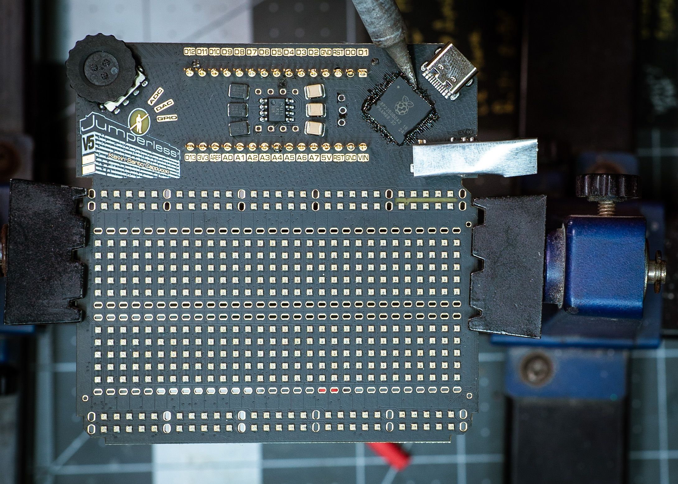
In this case, I switched out the LT1054CP charge pump with an almost pin-compatible LM2660MX. The issue was that the new circuit was too good, I was relying on voltage losses of the doubler/inverter circuit to supply +-9 V, whereas the LM2660MX was giving close to the ideal output of +-10 V (it’s doubling the 5 V from USB and also inverting it). The crossbar switches were still okay with the even more out-of-spec 20 V Vdd-Vee (versus the datasheet’s stated 14.6 V maximum), but they were getting pretty toasty.
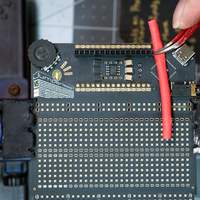
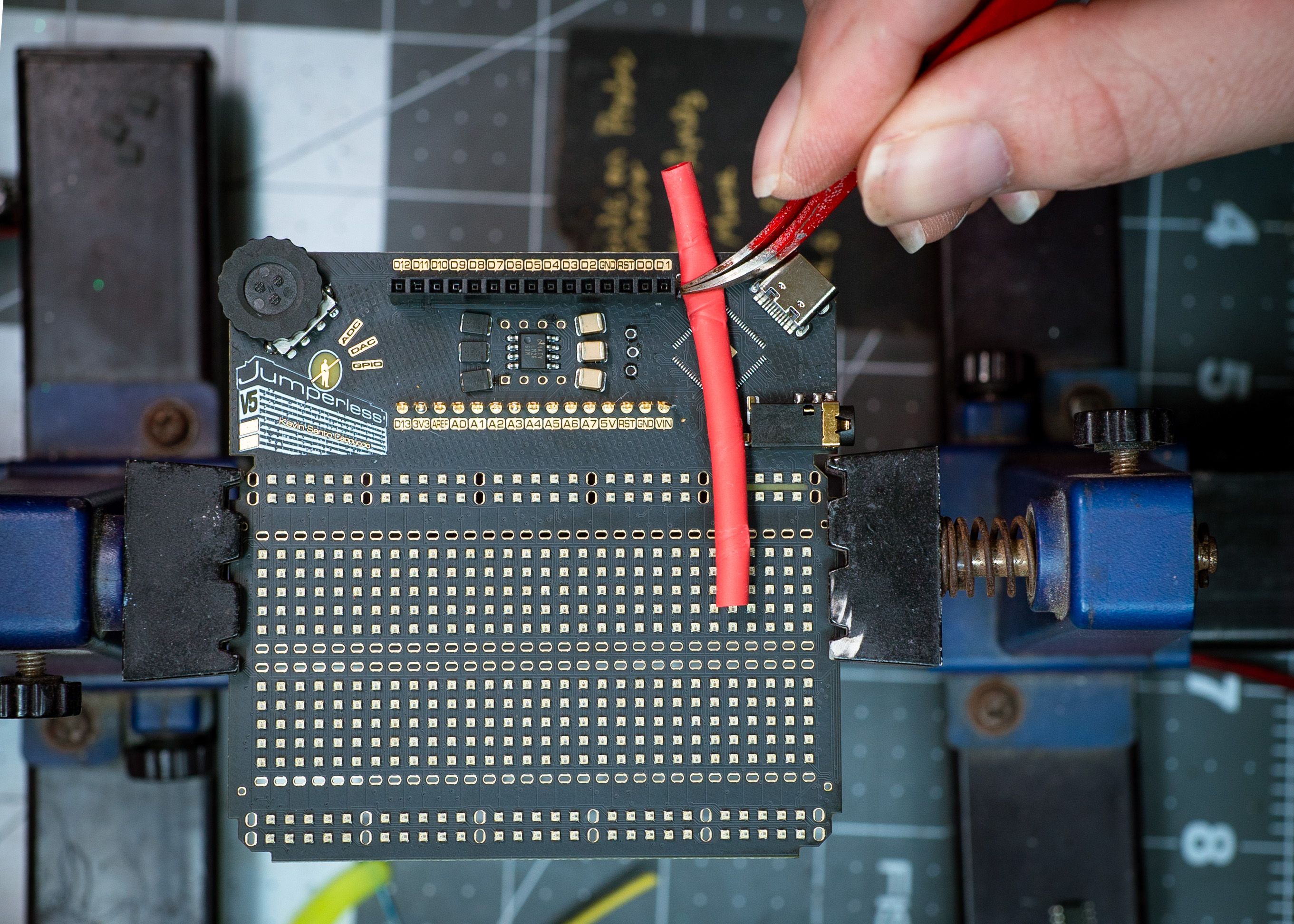
Fixing that just meant taking a trick from the early revisions of the OG Jumperless and dropping the outputs through a diode with a relatively high forward voltage drop. When I shop for diodes, I’m usually looking for low V forward, so I didn’t have any on hand in the right size, so as a proof of concept, I just threw a red LED in there:
The LED obviouly blew as soon as I drew a couple dozen mA from the supply, but it was kinda funny to see something that ridiculous work at all.
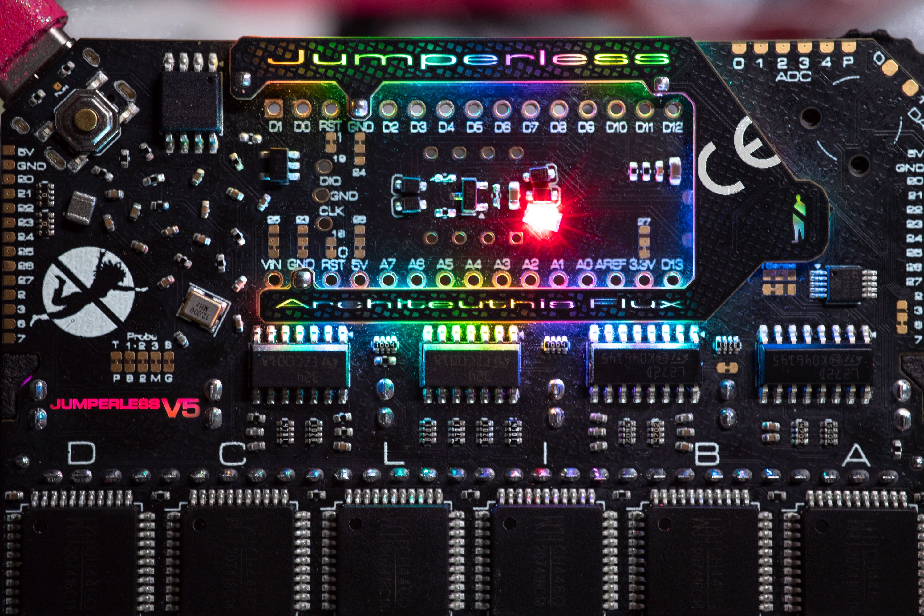
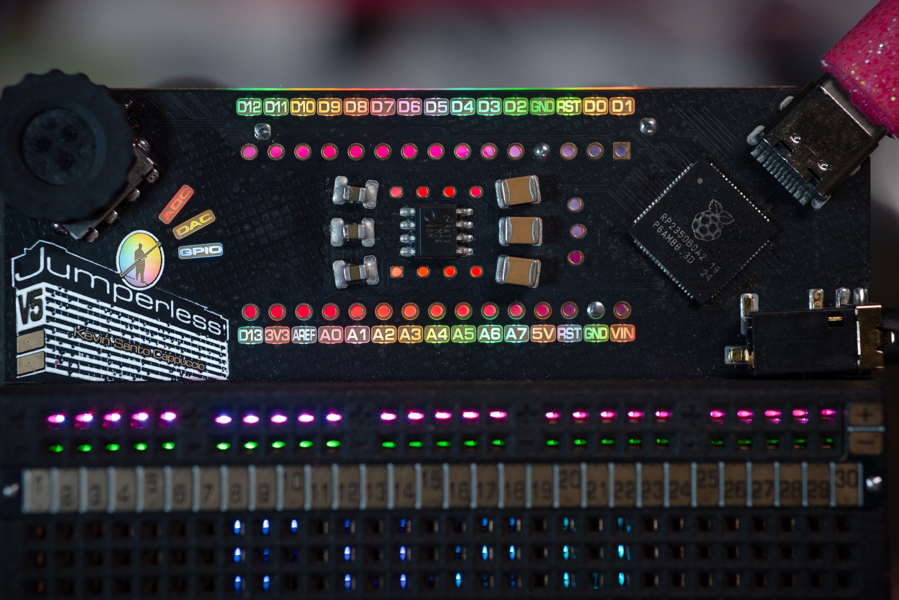
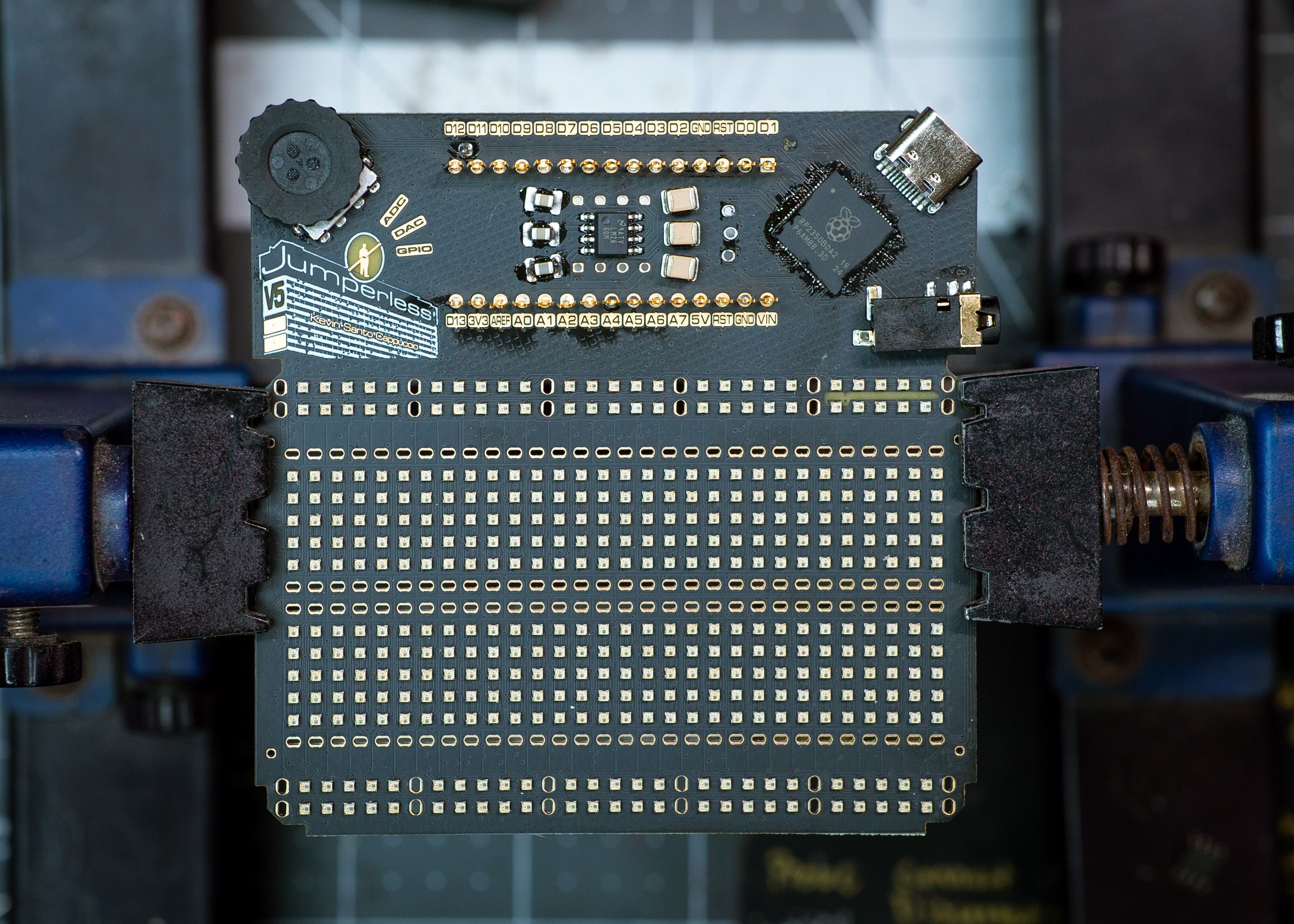
You also may notice that the text is backlit through the PCB now instead of a boring old silkscreen. No photons go to waste here. The light that bounces back from lighting the Nano header header pads on the front is recycled to light up the logo on the back. Which is checks notes all of it? Bummer…
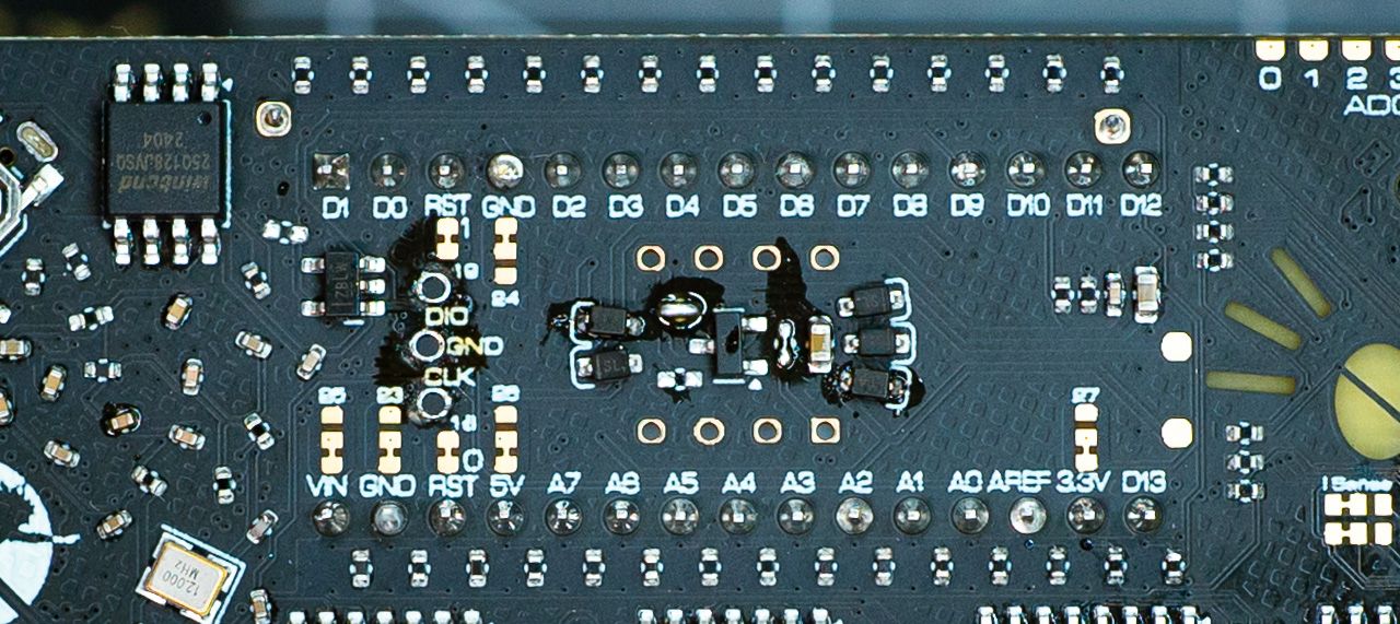
There should be uncoated FR4 windows in the places marked in yellow here:
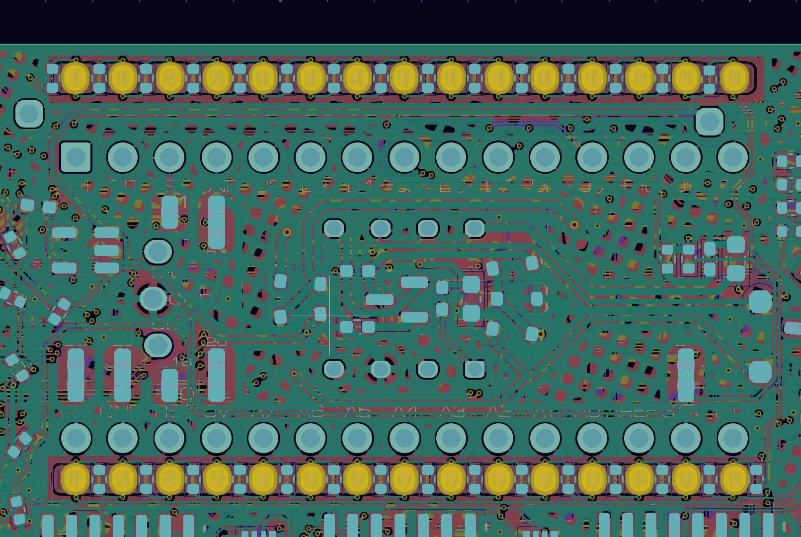
While routing this board, I moved the solder mask cutouts and forgot to put them back before I sent them off to the fab.
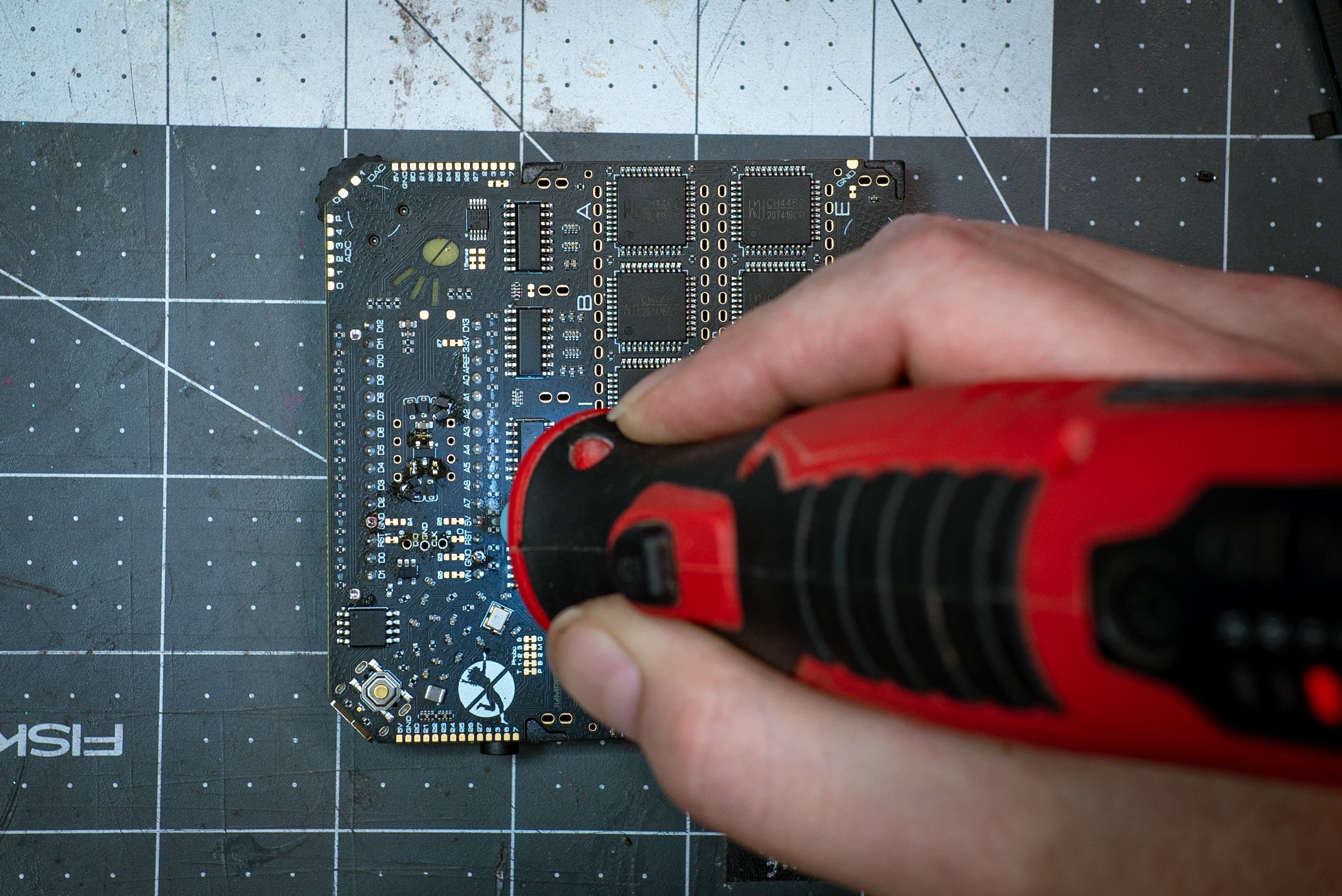
Welp, it’s nothing five hours hunched over a Dremel can’t fix:
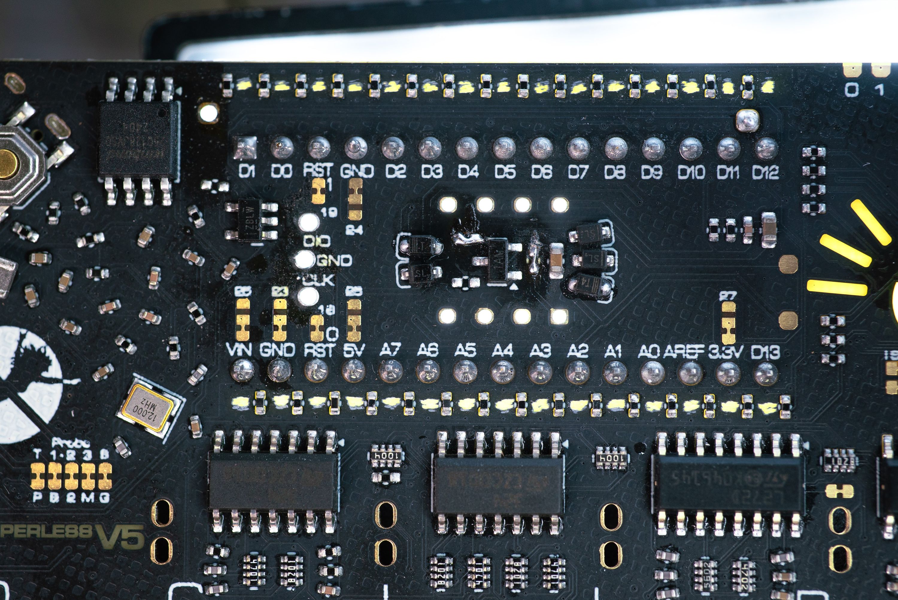
Some good came out of this, I found that smaller cutouts (even these jankily shaped ones) in the solder mask causes the light to bleed a lot less into adjacent pads, and overall looks like three per-cent better. Hooray.
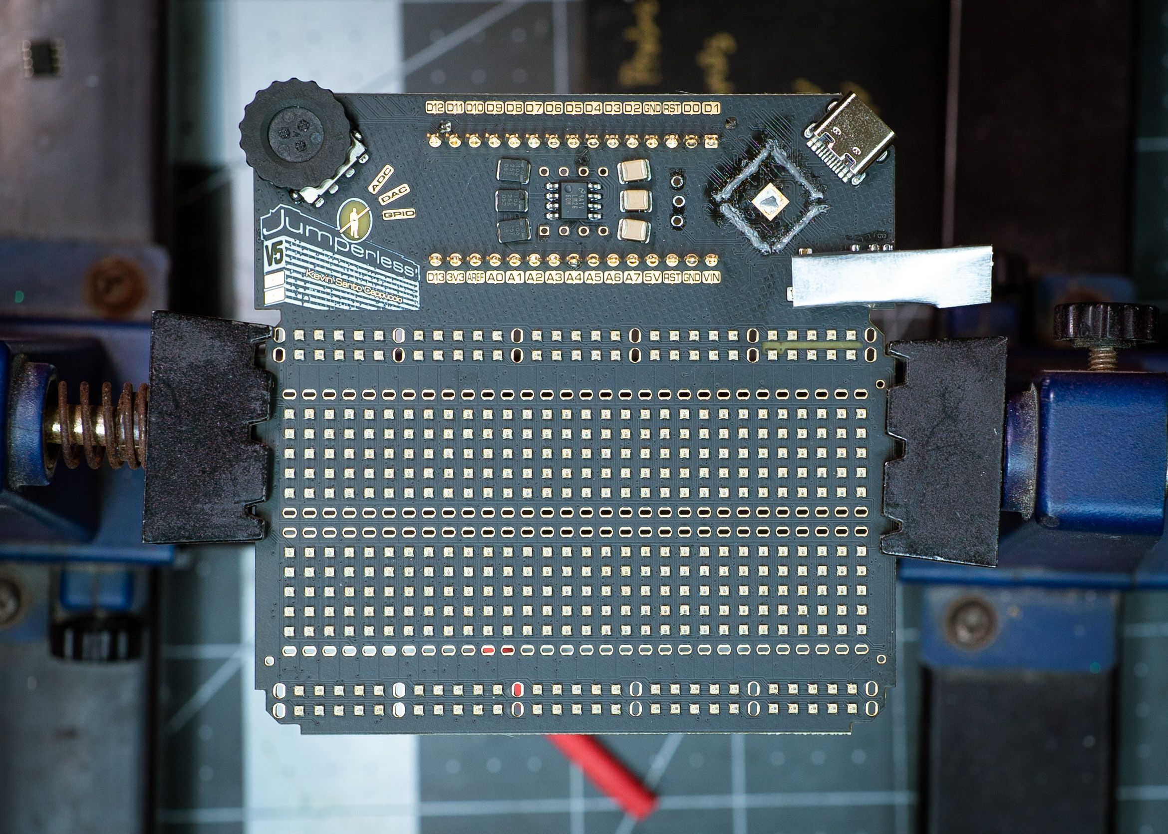
Adding The Smarty Bits (The RP2350B)
If you’re wondering how I was able to get boards fabbed with an RP2350B before they’re widely available as bare chips to the public, the answer is that I didn’t. These chips were handed to me as samples by the awesome people at the Raspberry Pi booth at DEFCON. I ordered the boards with an unpopulated footprint and soldered them on myself.
Soldering a QFN-80 without a stencil and a bunch of already populated parts is way more doable than you may expect. There’s no "right" way, just a nearly infinite number of ways that’ll work Here’s the one I used.
There are populated parts on the back already, so a hot plate isn’t really an option here, so we’re using hot air. The first step is to remove and/or protect all the melty parts. Turns out you can pry off the plasic shroud on female pin headers, that red heat shrink is there as a pad so I don’t scratch the board.
Then I cover the headphone jack with some metal Dymo tape and put lots more solder paste than you’d probably expect over all the pads.
Plop the chip down in the correct general area and hit it with the heat of a thousand suns.
Once everything’s melted, I poke at it with the tweezers while keeping everything hot. You can kinda scootch it around and it’ll snap into place once everything lines up. Smaller parts will do this without any poking but this one is a little too big to float on solder. Once it’s in the right place, I push it straight down and these little balls of excess solder will squeeze out the sides, I take the heat off and keep holding it down until the solder freezes.
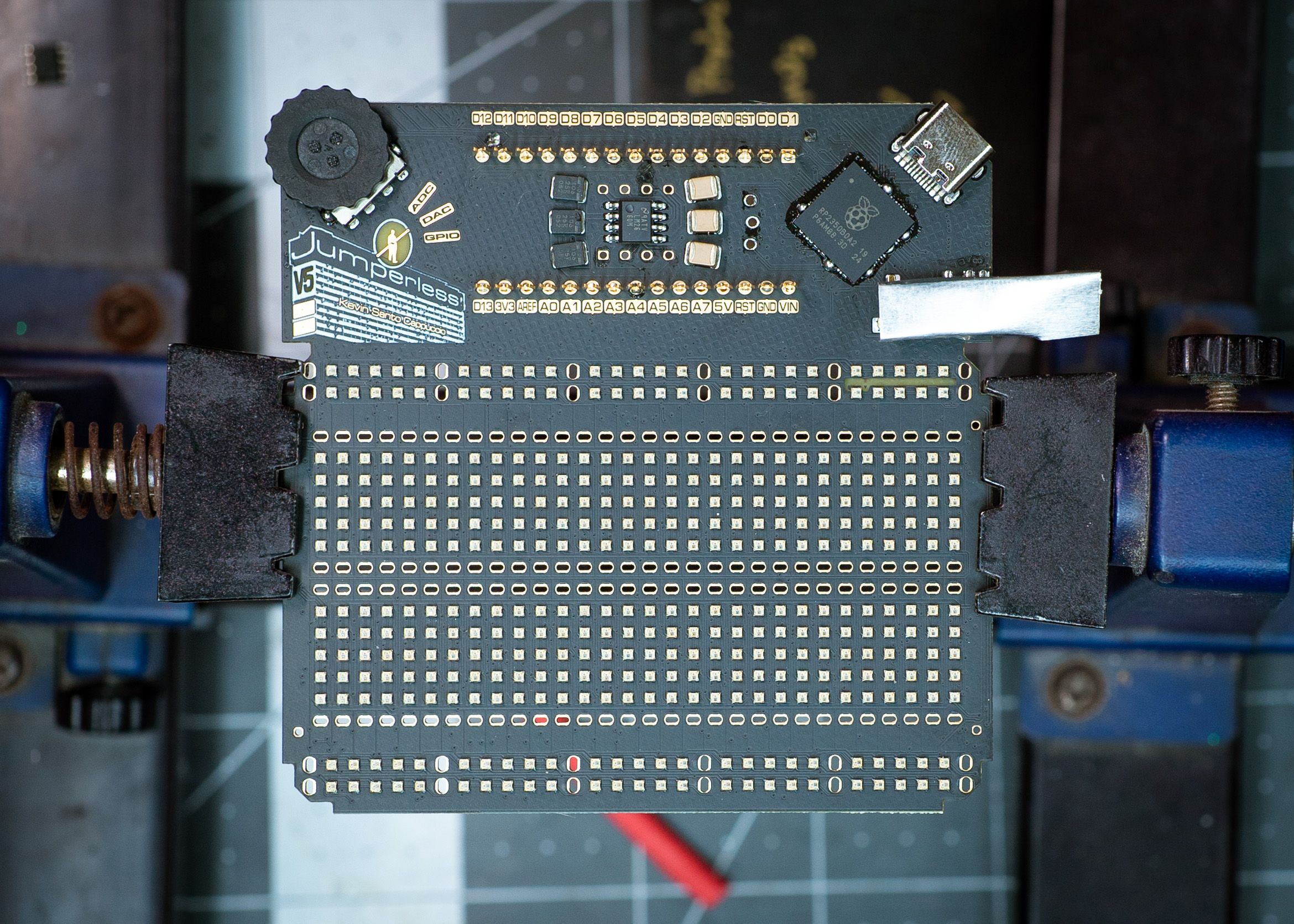
Then you can just come in with a clean, fairly pointy soldering iron tip and vacuum up the little balls. Surface tension rules.
A couple of rinses with my favorite heavy-duty flux remover and you’re good to go! I can’t recommend this suff enough, it’s amazing. It’ll melt some types of plastic though, so be careful. Also, my dog particularly hates the smell of this stuff, she leaves the room every time I use it and waits until I’m done to come back.

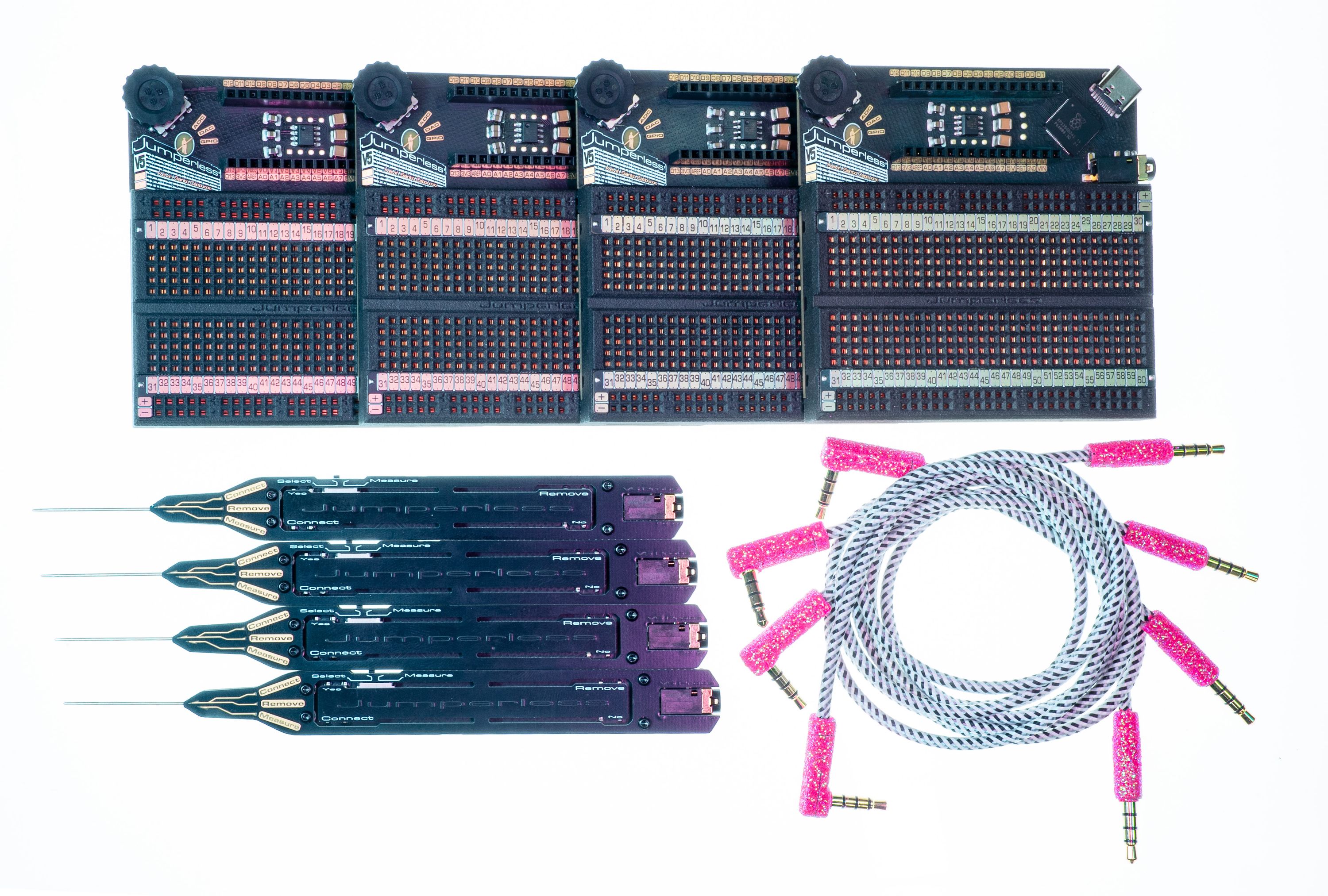
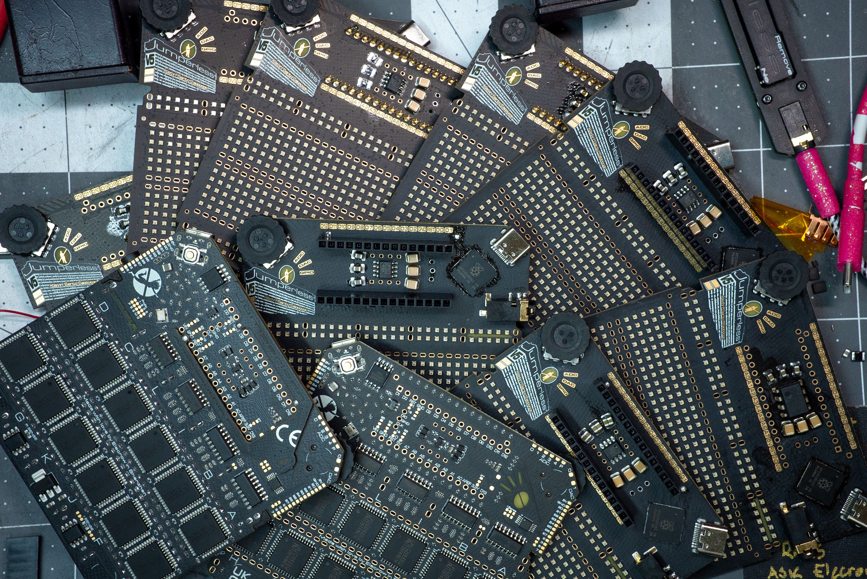
Now I just need to assemble the rest of these parts:
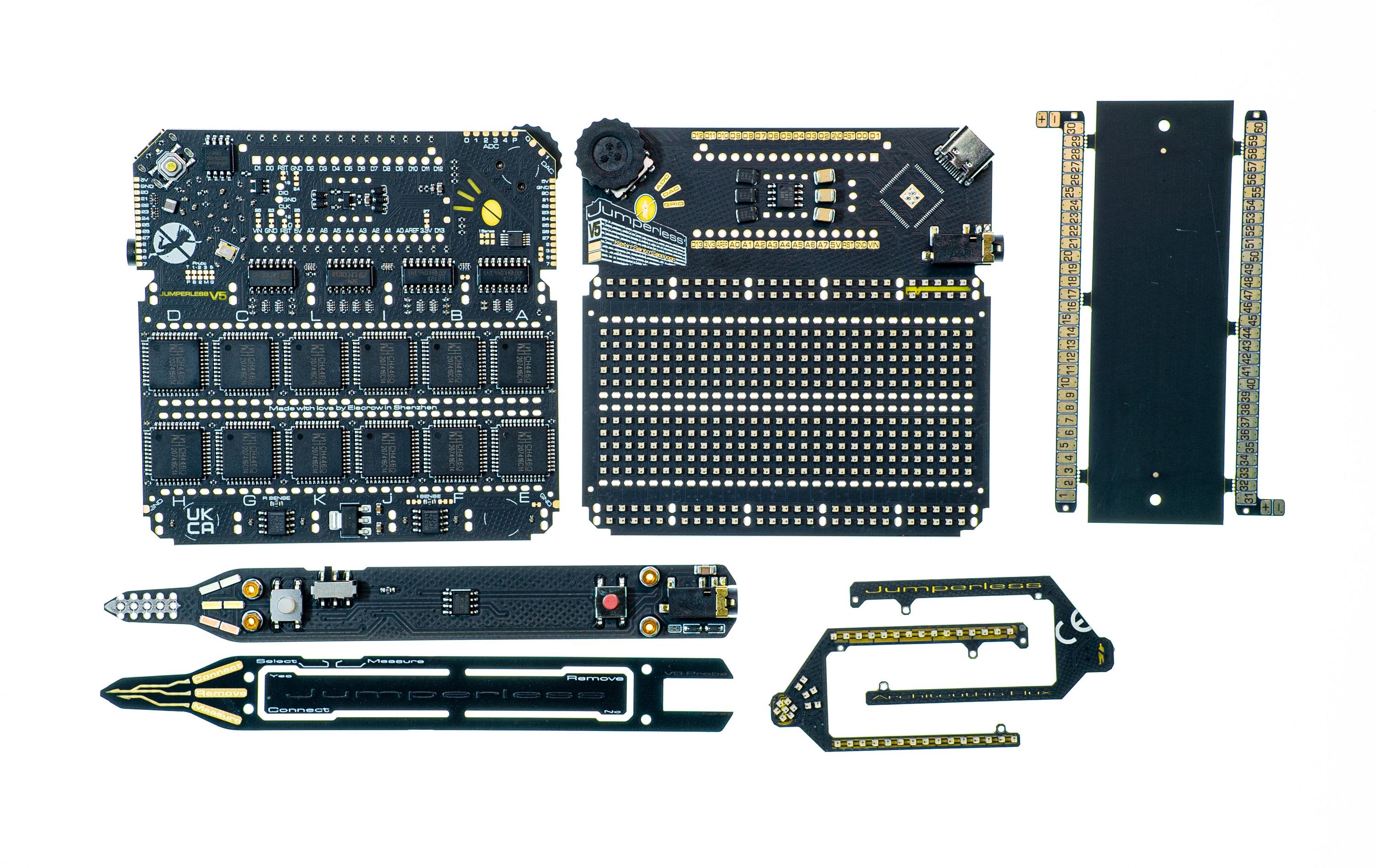
You’d think I’d be immune to the appeal of a fully assembled Jumperless V5 by now, but I’m very much not. I can’t wait for the full production fun so I can lay on a pile of them like:

Maybe I won’t try it with the probes though…

Anyway, if you’d like to hear what the beta testers are saying about using their Jumperless V5, they’ll probably be giving me their feedback and bug reports on the Jumperless Discord server or GitHub.
If you want daily-ish updates on my quest to make Jumperless V5 the single most useful and fun thing you have on your workbench, I’m always posting fun little tidbits on Twitter/X and Mastodon.
Dictated but not read,
Kevin