Project update 2 of 10
How modular entropy multiplication works in the real world
Simulations
The software simulation shown in the campaign video is great - but simulating modular entropy multiplication has a big downside as there is no entropy source.
You can spot repeating patterns when you take a close look at the analog stage of the TINA simulations Bill published on GitHub.
The swift simulation from Z1FFER on openrandom.org uses the ARC4 cipher to also simulate some entropy. Nevertheless it’s still theorical and not very close to any hardware implementation.
Real world
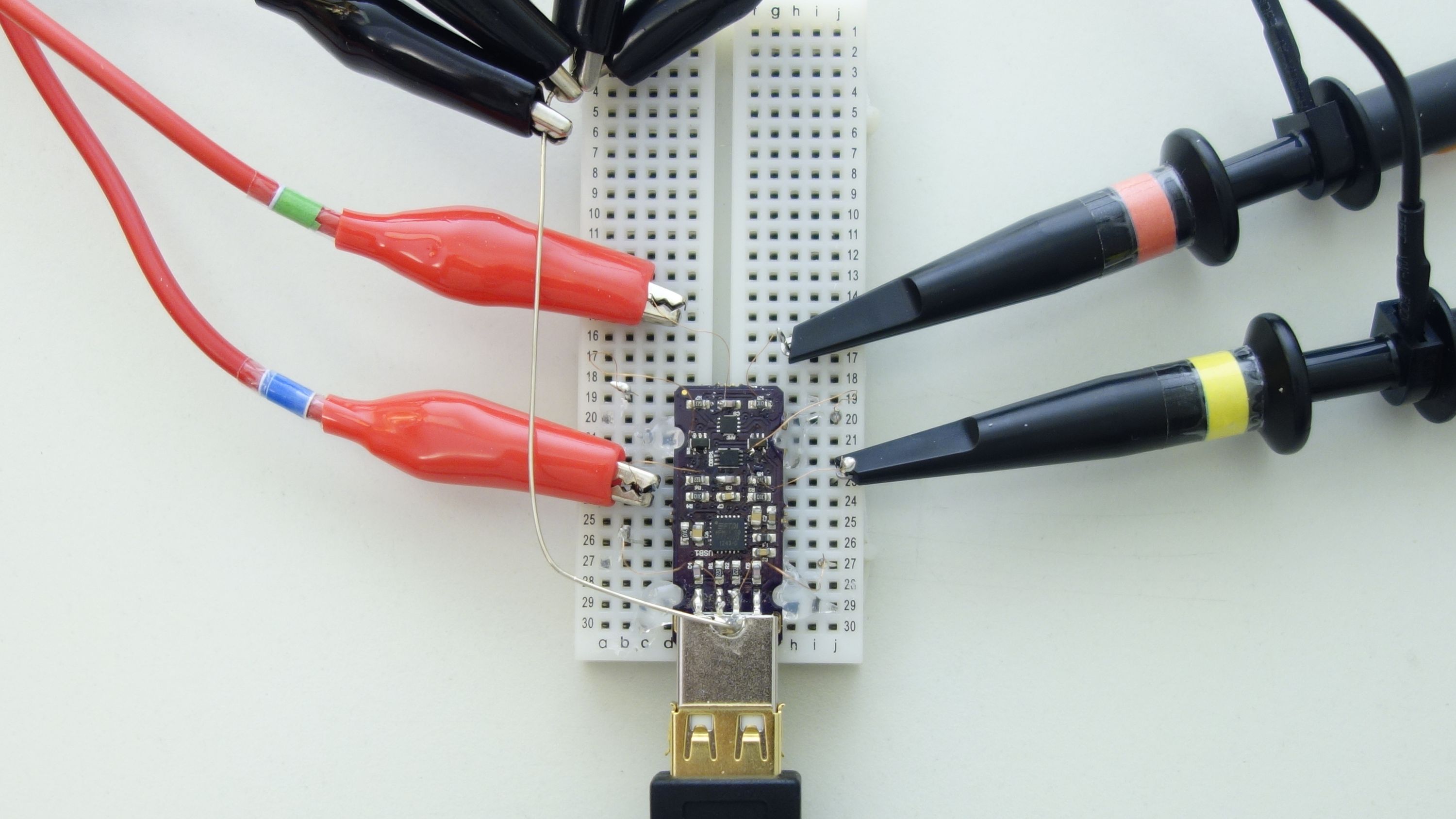
To see how it performs in reality I got a 4 channel oscilloscope and bonded an Infinite Noise to a breadboard to start an "attack":
All the probe cabling adds a lot of capacitance, so the readings may not have been 100% accurate. Indeed, the health monitoring - or more precisely the test for more than 20 consecutive 1’s or 0’s stopped my attempts several times, as all the capacitance overloaded the comparators output.
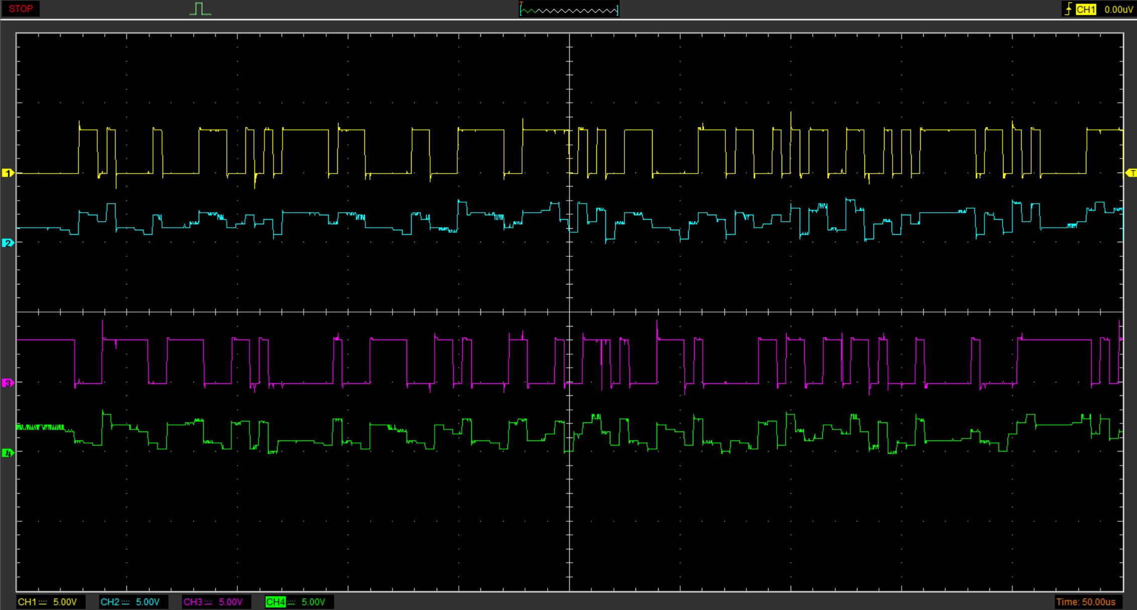
Thus I was no able to capture long-term data to evaluate the randomness as intended, but I was able to get it running for some plots and couldn’t find any repeating patters. Except for (maybe) in the startup sequence which was also very suspicious in the simulations, as we start with zero entropy (or state) - just like the simulations.
This part of the experiment isn’t that useful anyway, as the randomness has been verified with dieharder, ent, rng-test and some other tools already. The warmup-time is insignificanty short, but as you can see it may take some cycles to get the first entropy into our loop.
What you see are the digital and analog outputs of both multipliers in the circuit.
| Channel# | Connected to | D/A | Multiplier# |
|---|---|---|---|
| 1 | COMP1 | Digital | 1 |
| 2 | C8 | Analog | 1 |
| 3 | COMP2 | Digital | 2 |
| 4 | C9 | Analog | 2 |
Mixing
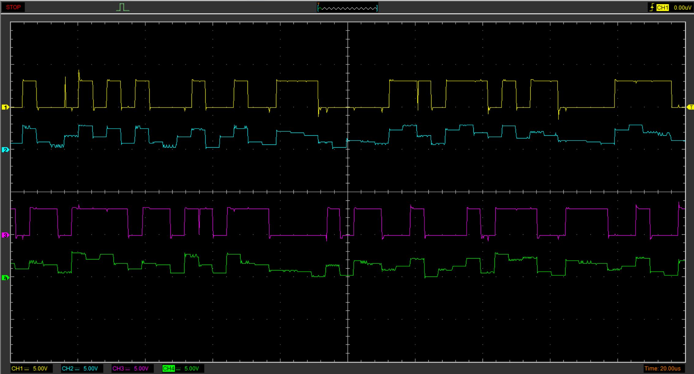
As you can clearly see in the second plot with 20 µs per division, the analog signal does not change fast enough to change the digital output every cycle. A single multiplier circuit produces sequences of 1’s and 0’s of a random length. Sometimes it takes only one cycle, sometimes five to flip the output state.
The driver takes alternating readings from both multipliers to compensate this behaviour of a single MEM and ensure both multipliers are working as expected, as the entropy will be halfed when one is not working.
Note: See the Update #3 for more explanation.
As a next step, I’ll try to get a reading from both digital outputs in parallel with the USB data line, so we can also see how this mixing works out in practice. When using X10 probes for the digital outputs its also possible to take readings without overloading the comparator, so it doesn’t stop operation because of "tamper-events".
The new oscilloscope should be capable of this, but I’m waiting for another pair of X10 probes to arrive. USB is way too fast to sample it with alligator clip probes.
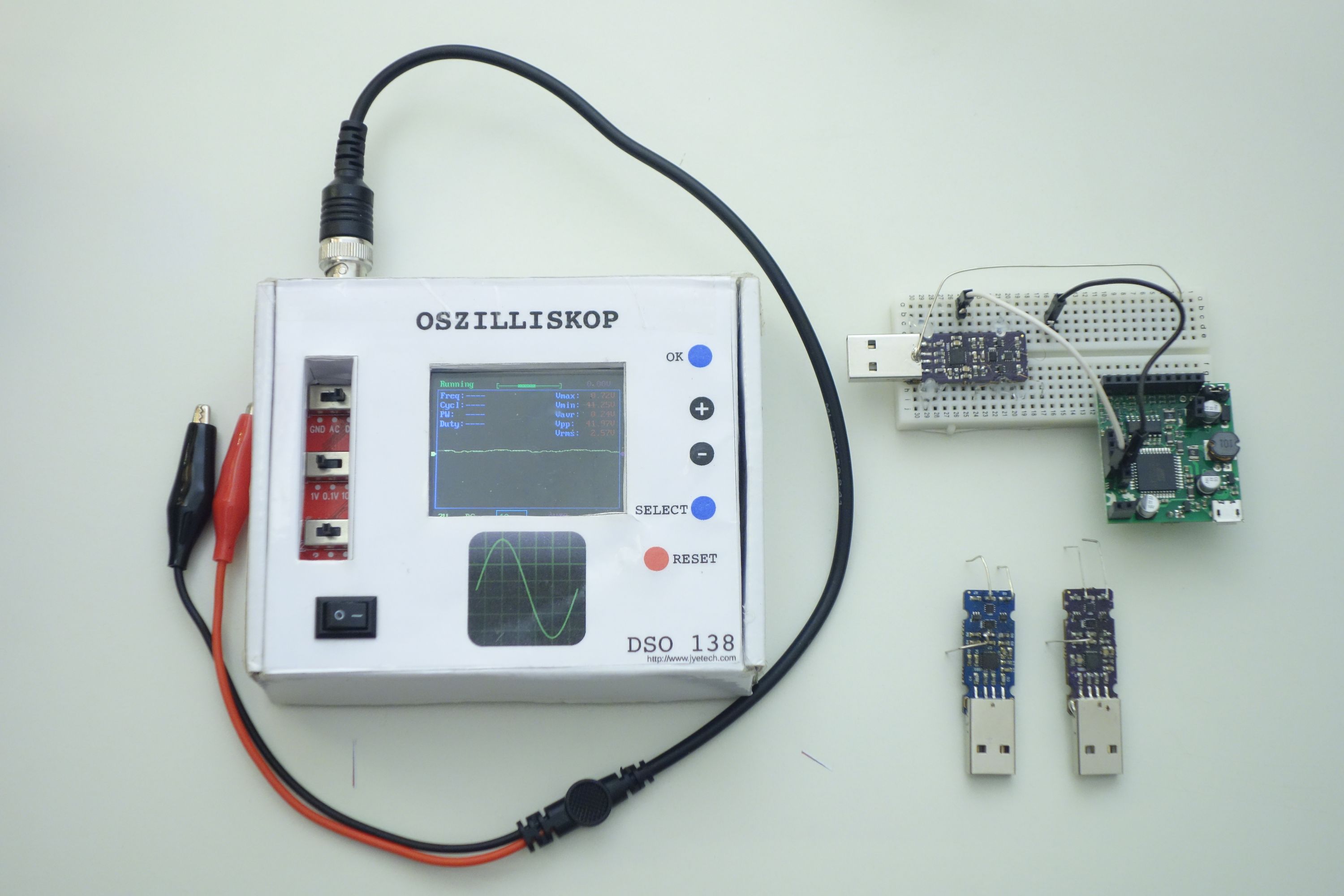
Sadly, my previous oscilloscopes would’t have done this job. One is the popular DIY DSO138 and the other one an EspoTek Labrador I got from Crowd Supply. Both cover the frequency range, but have too low bandwidth for the analog signals I wanted to show. Using the Labrador at higher frequencies (>50 kHz) with both channels worked, but jumper wires are really bad probes, resulting in a lot of interference.
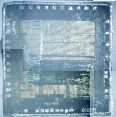
Decapping
The two Infinite Noise’s in the lower-right have been destroyed during my attempts, as I ripped off copper pads from the PCB because of the thick wires I had used. That’s why you almost can’t see the 0.1 mm (0.04 in) wire on the breadboard installation above.
They did not die in vain, as I will desolder the FT240X USB chip and use them for another experiment. You will see all results in another update hopefully soon. If you wonder why I’m doing this, stay tuned!
Don’t worry, I won’t use any hydrofluoric acid.


